Hacking the HP Z840 Motherboard into a Standard Case
Come with me in this journey of frustration hacking the HP Z840 motherboard into a standard case :)
It feels like a hundred years ago when, in need of a new computer which had to be cheap and powerful, I stumbled across that post we all know about hacking the Z800 motherboard into a standard case.
I read it all (included the tons of comments pages) in one go, and launched myself into the task. All purpose and motivation, I bought the motherboard and all the pieces needed, and in 4/5 weeks I had it running. That computer served me for 5 years, until the motherboard failed and I replaced it with a Fujitsu R640 which, by numerous reasons, needs to be replaced now.
So I thought... fine, sure there is the equivalent for the Z840 now. I just have to find it and go through the same process again, no big deal. But yeah, you know, it is not there. Or at least I could not find it. What I did find was a lot of people asking for it, asking for pinouts of non standard ports, fans, weird post errors... All the usual stuff.
And I forgot about it. If it is not done already, it cannot be done. Let's find another motherboard and go with a different build.
I went to eBay and started to search for 2011-v3 dual socket boards to buy. And of course what I found was very expensive Asus / AsRock / Gigabyte boards, which will not do, and one very cheap Z840's. Like very cheap. Like 80 euros. Like I was clicking the buy now button even before I thought about it. Feck it, I will figure it out. I'm a fecking engineer. I can do this.
Oh boy, here we go again.
1. The Motherboard
The board itself came in the mail two weeks after, and it looked brand new.
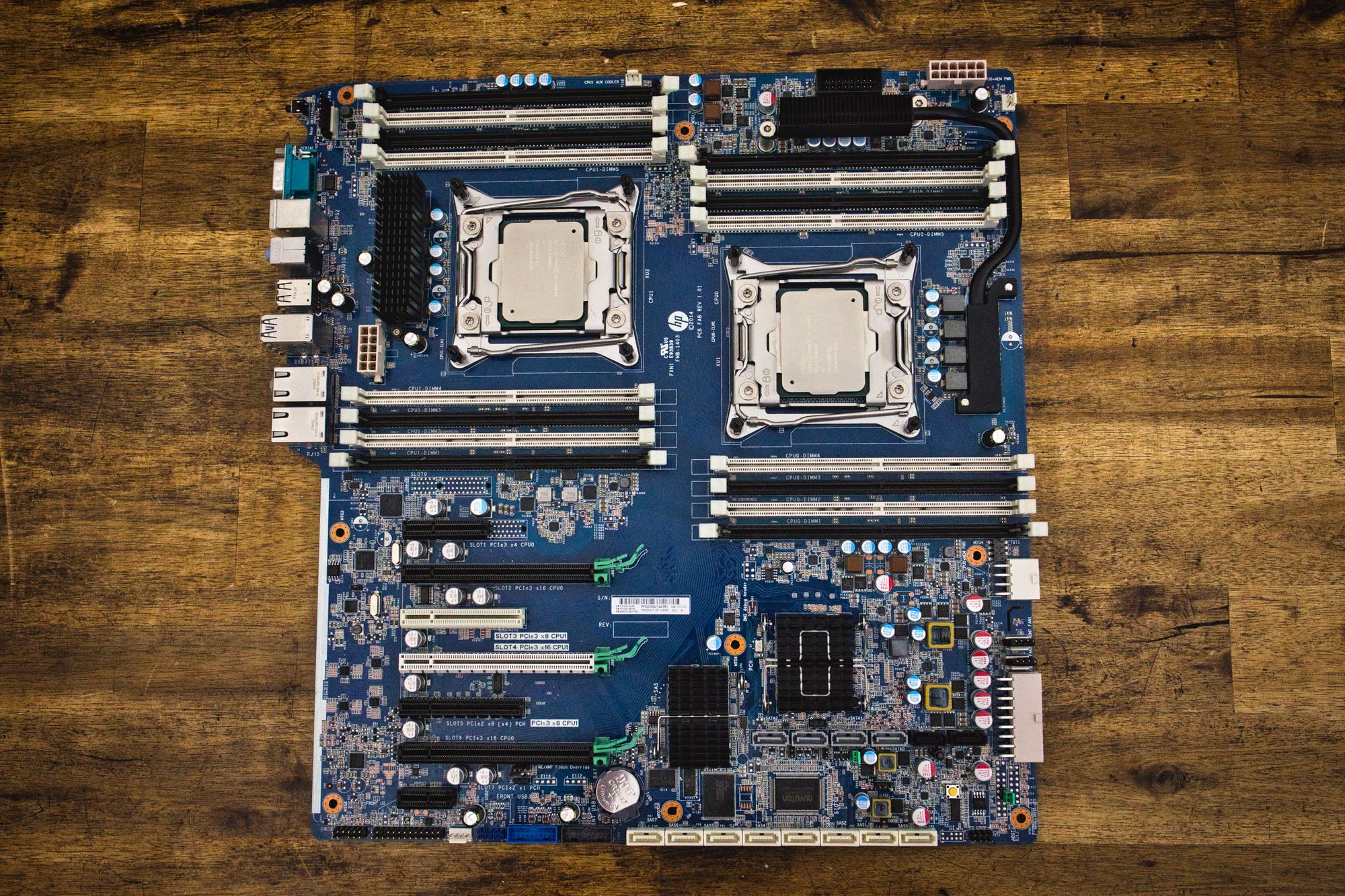
This is not your standard MATX board, this is huge. At 36x33 cm it is even bigger than the EATX format. That is something to consider, as most of the cases you can buy for a reasonable price will not do.
It is packed up with tons of features. Lots of SATA and SAS ports, internal USB and USB3, 2 2011-v3 sockets and 16 DDR4 slots. In the external IO part it is a bit shy though:
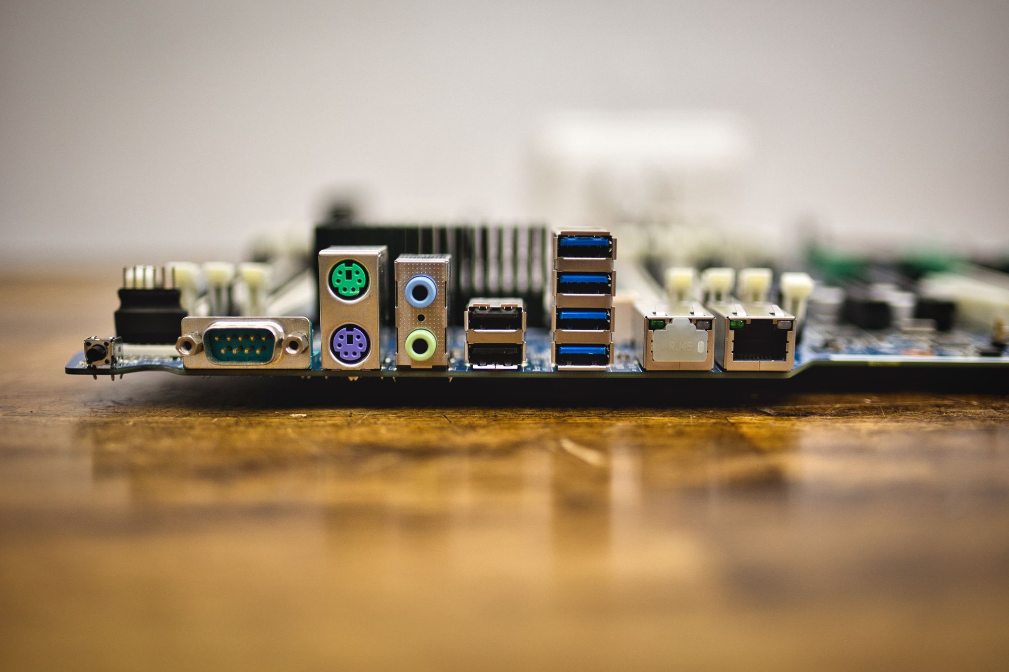
Just 6 USB ports, 4 of them USB3. A couple of PS2 connectors for old keyboard and mouse, and a couple of 3.5mm jacks for microphone and stereo audio. The serial port interface is anecdotical, but nice to have for some people, I guess.
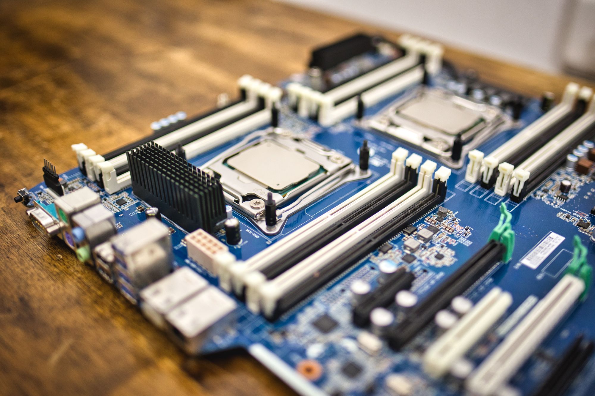
We can also see the two 2011-v3 (v4) sockets and the 16 DDR4 memory slots (8 per CPU):
Where this board shines, at least for me, is in the PCIE part:
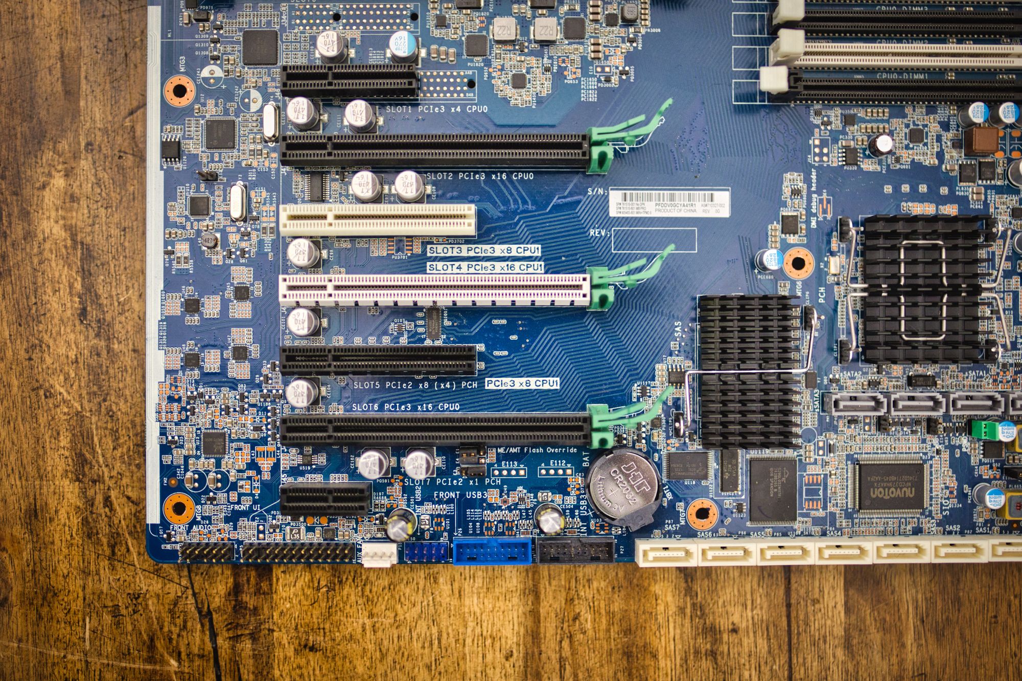
When you load the board with two CPUs (as it should) you get a lot of lanes for your cards: 36 lanes in CPU0 and 32 in CPU1, all of them PCIE3. Quite nice considering the limit of V3 intel architecture is 40 lanes per CPU, and we have to add the lanes used for the SATA and SAS interface, the USB and network controller, etc.
There is no m.2 port for NVME drives, but that is easily solvable with a 15 euro PCIE 4x adapter, as we will see later, and the speed will probably be better this way.
It is almost perfect... until you try to plug it in and you discover that you cannot. And even if you can, the board will complain about not having all the missing parts around. We have work to do here.
Power Connectors
All the power connectors in this board are proprietary, and we have 4 of them. We have to be careful here, as for example the 8 pin one looks exactly as the standard CPU power connector but the pinout is very different, so we can burn the board very easily.
Using my 20 euro multimeter and a lot of time, I've been able to figure out all the pinouts for these 4 connectors. They look like this:
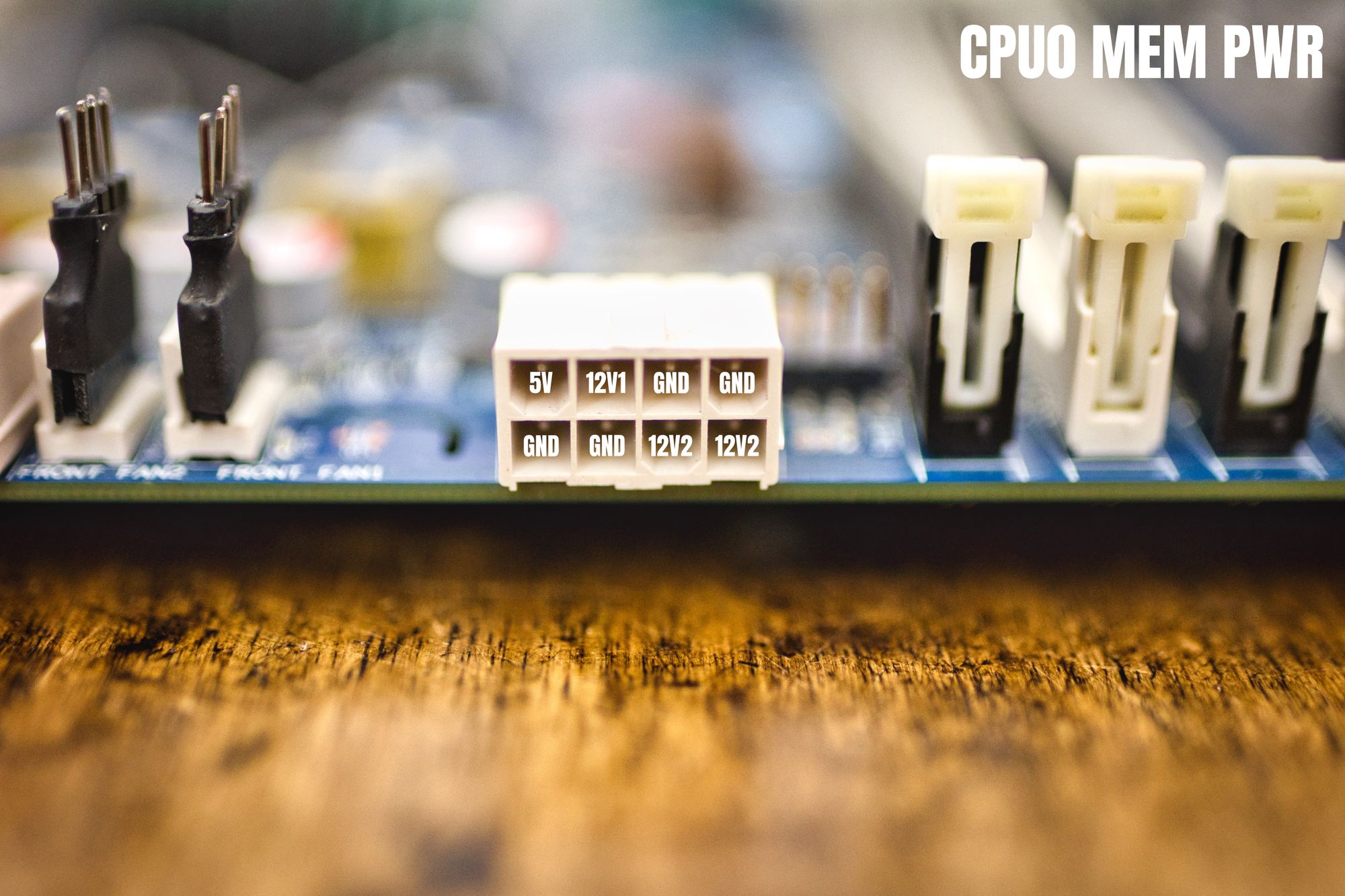
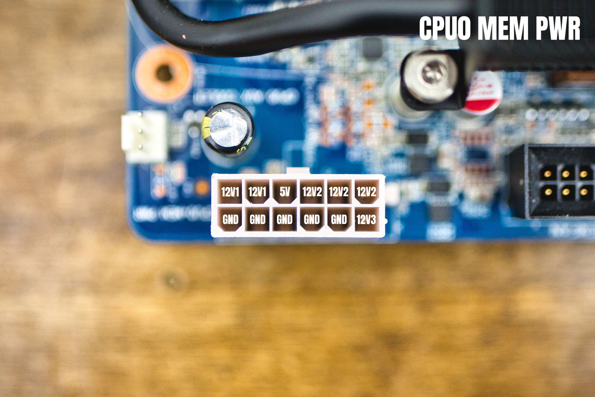
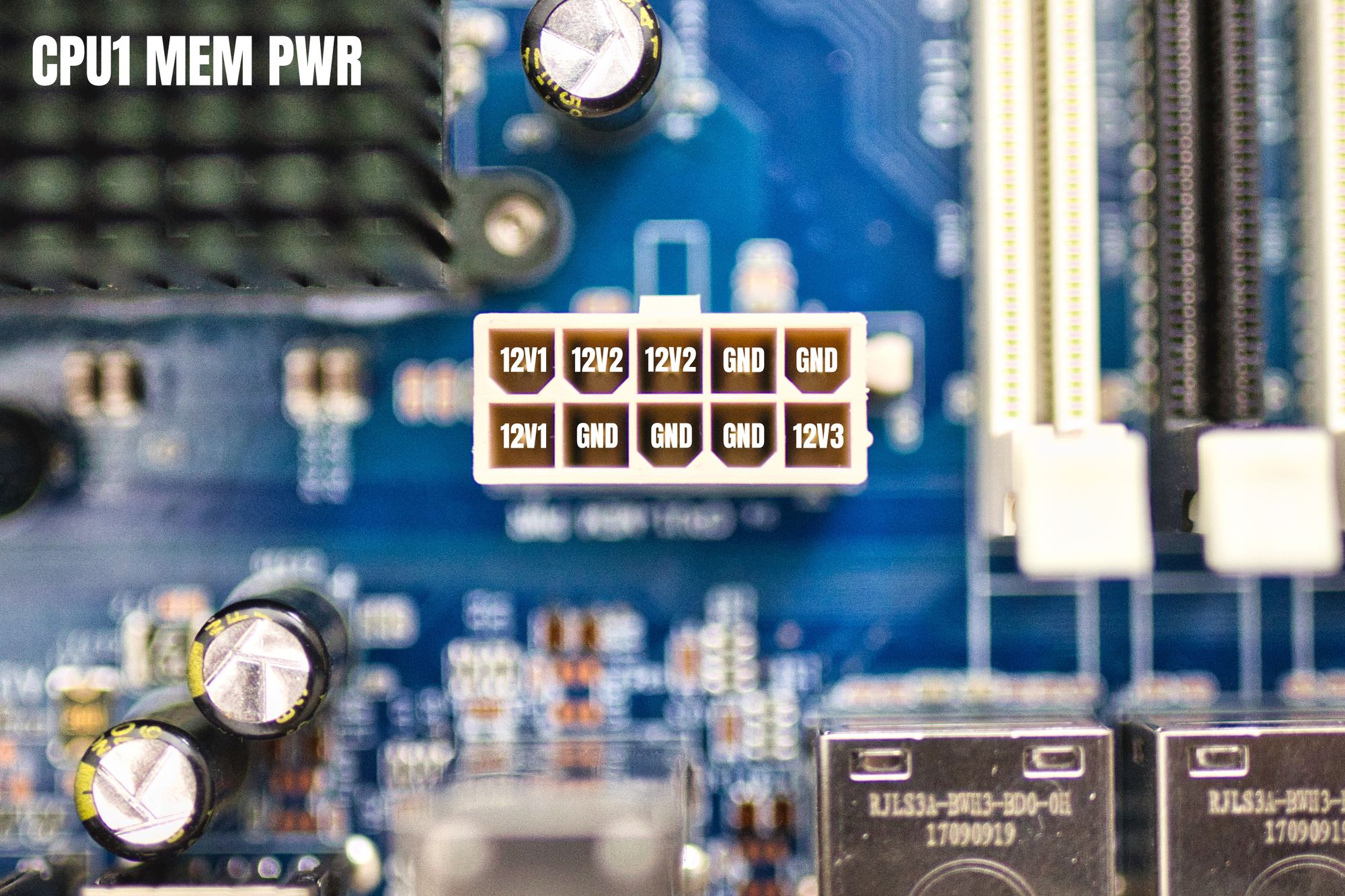
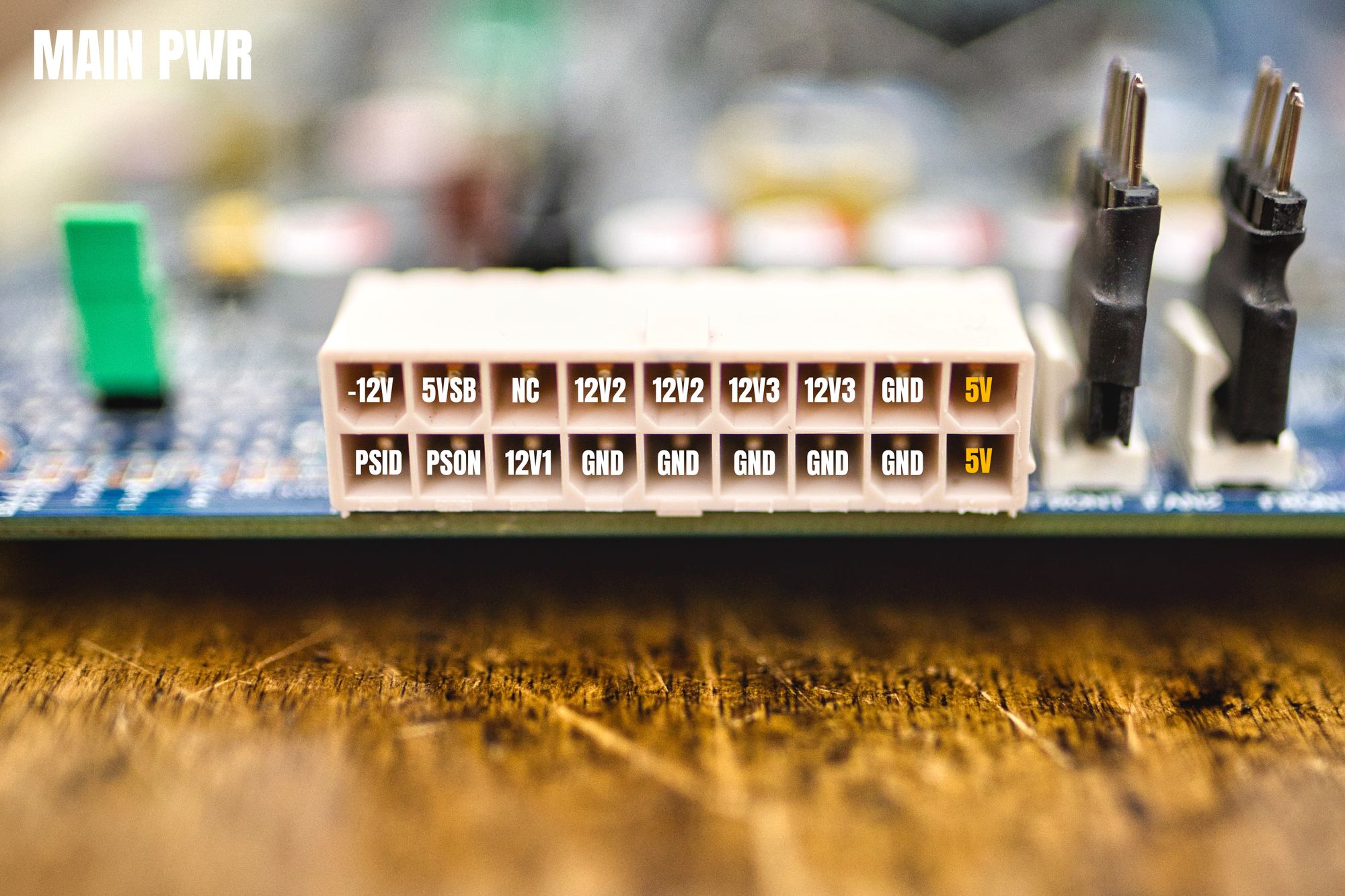
Keep in mind that in each power connector, voltages belonging to the same segment have to come from the same power rail in your power supply. So for example two pins marked as 12V2 have to come from the same 12V rail in your PS. This is very important. No need to keep this rule across different connectors, just in each one by itself.
Also, please note that those two orange 5V pins in the last connector are output voltages, the board is generating the 5V for you, so please don't connect them to the 5V in your power supply.
The -12V, 5VSB and PSON are the standard controls signals you can find in any power supply, you can just connect them and forget they exist.
The PSID pin, on the other hand, is different. This is a signal used by the motherboard to know the amount of wattage the power supply can provide. If you are not using high power CPUs you will be fine just leaving this pin floating (not connected), but if you are planning to bring the big guys to play, the motherboard will complain at POST about the power supply not being powerful enough. To get rid of the error you have to put 1.25V in this pin. I can explain you the process I followed to came up with this value, but is long and tedious. Just set that pin to 1.25V and see your error disappear. Of course, you have to make sure your power supply is powerful enough to carry on with the demand in your system. If your PS is too weak, it will overheat and it will just go down or, much worse, it will burn.
The NC pin is, of course, not connected.
As you can see, this is a 12V only system. It does not need 3.3V nor 5V. There are two connectors requiring 5V as reference voltage for the RAM, but the motherboard is providing two 5V pins in the biggest connector. You can just interconnect them, but it will mess up your cables, as they will be dependant on each other.
I've preferred to leave the 5V output pins not connected, and use the 5V generated by the power supply in the other two cables requiring them.
Fan Connectors
We have mixed connectors here. There are 4 of them (3x 4pin and 1x 3pin) which are standard. There is one having six pins which is almost standard. And we have one 16 pin connector which is completely made up.
We need to feed valid tachometer signals to these connectors or the board will also complain in POST about missing fans.
The pinouts are as follows:
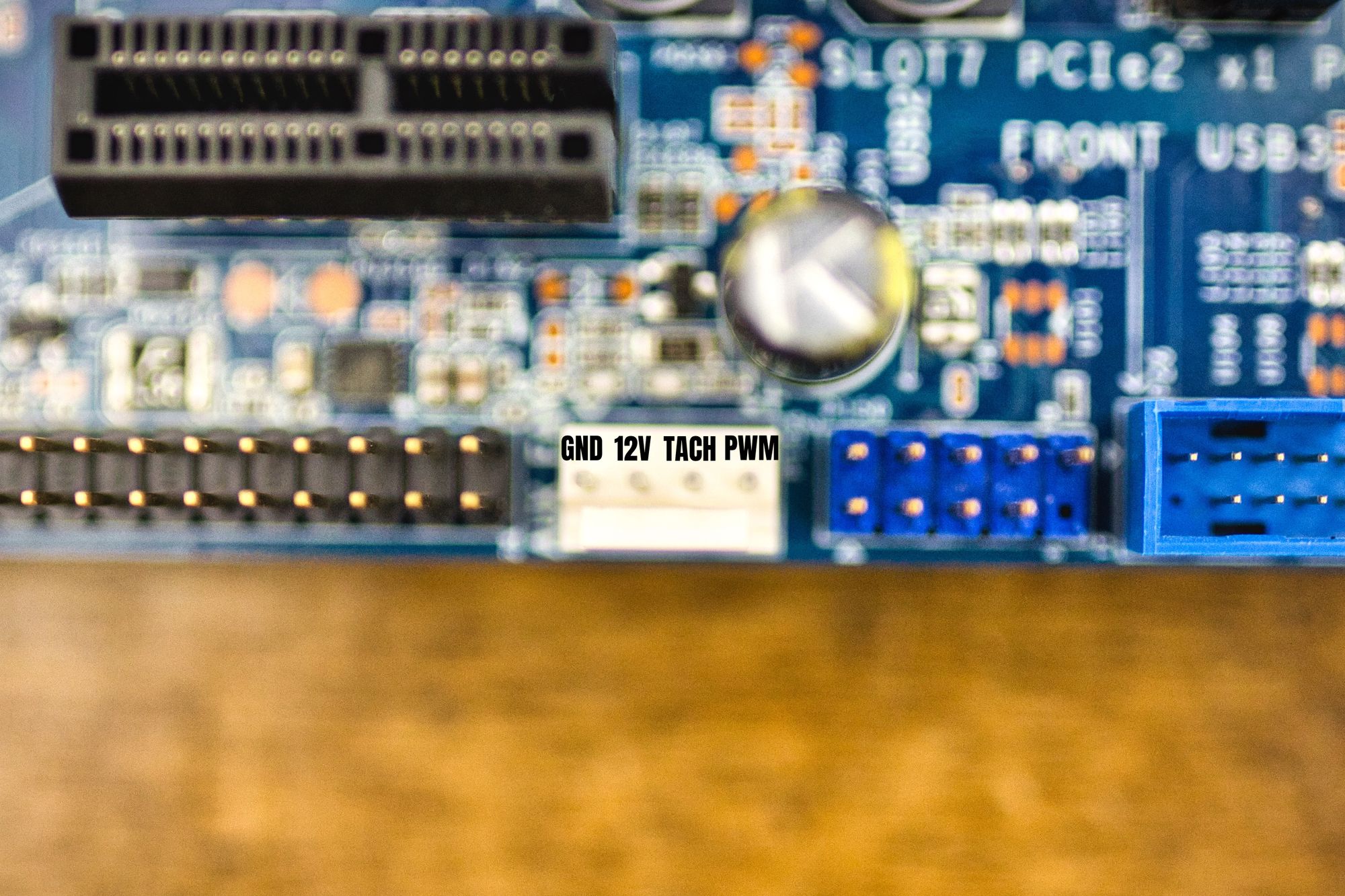
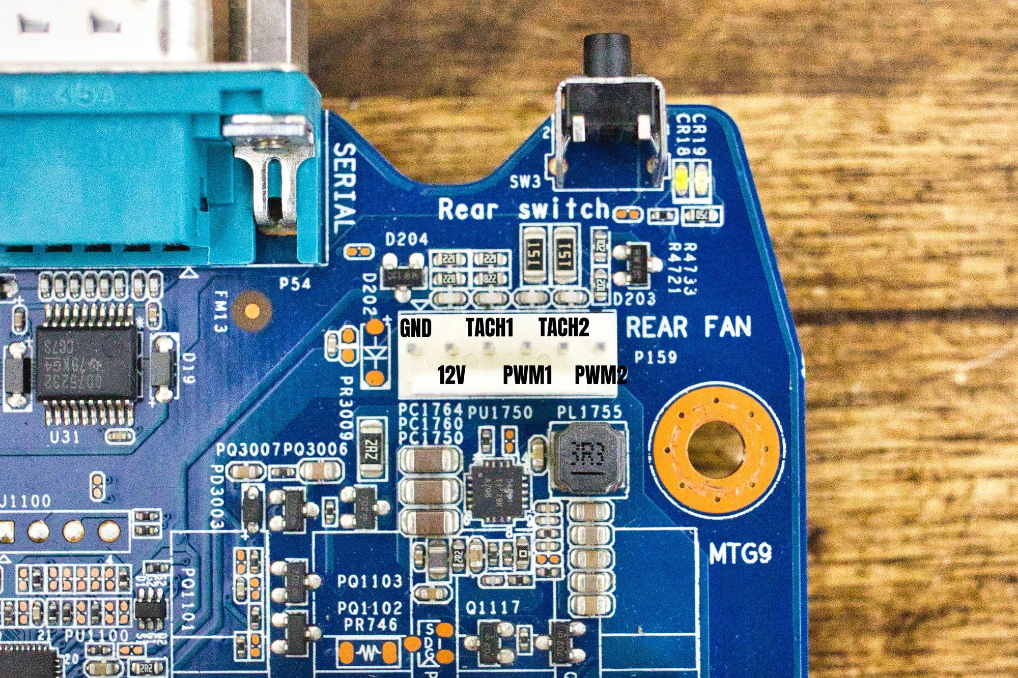
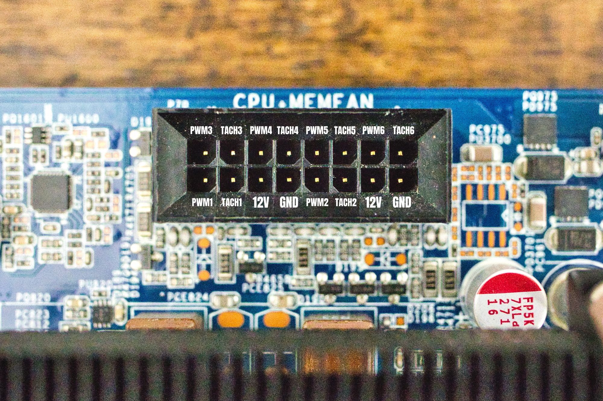
We have three connectors of the 4 pin type. Two of them are mandatory, they are the two connectors at the right part of the board labelled as front fans. All the tach signals in the 6 pin connector and in the 16 pin connector are mandatory.
We can connect the tach pins directly to one or multiple fans, or we can just connect one square signal generator and forget about them. Your choice.
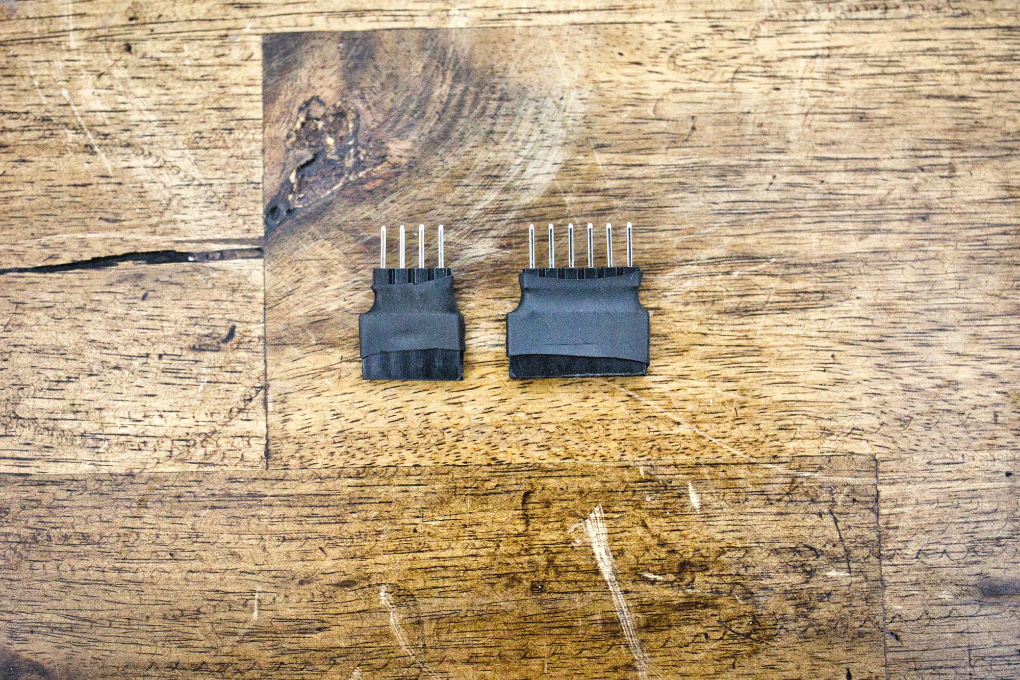
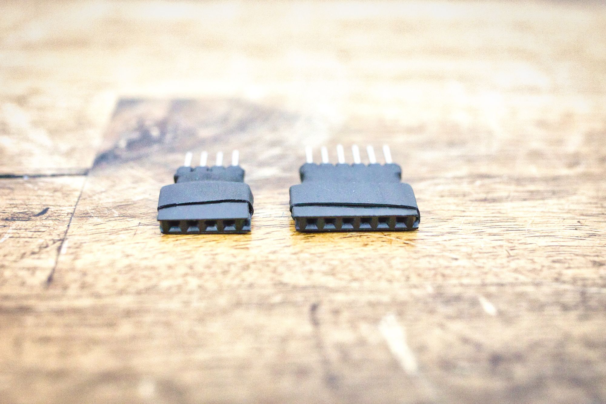
The 4 pin connectors, while being standard electrically, are a little bit different physically. That will prevent the normal 4 pin fan connector to go down completely on the pins, making a flaky connection. To solve it, I've made very simple adaptors using standard male and female pin strips. They look like this:
Temperature Sensor
One little thing we need to take care of is the temperature sensor. This sensor is included in the cable that goes from the motherboard to the front panel connector in the original case.
If the sensor is not connected, the motherboard will spin the fans at top speed all the time, and of course we don't want that.
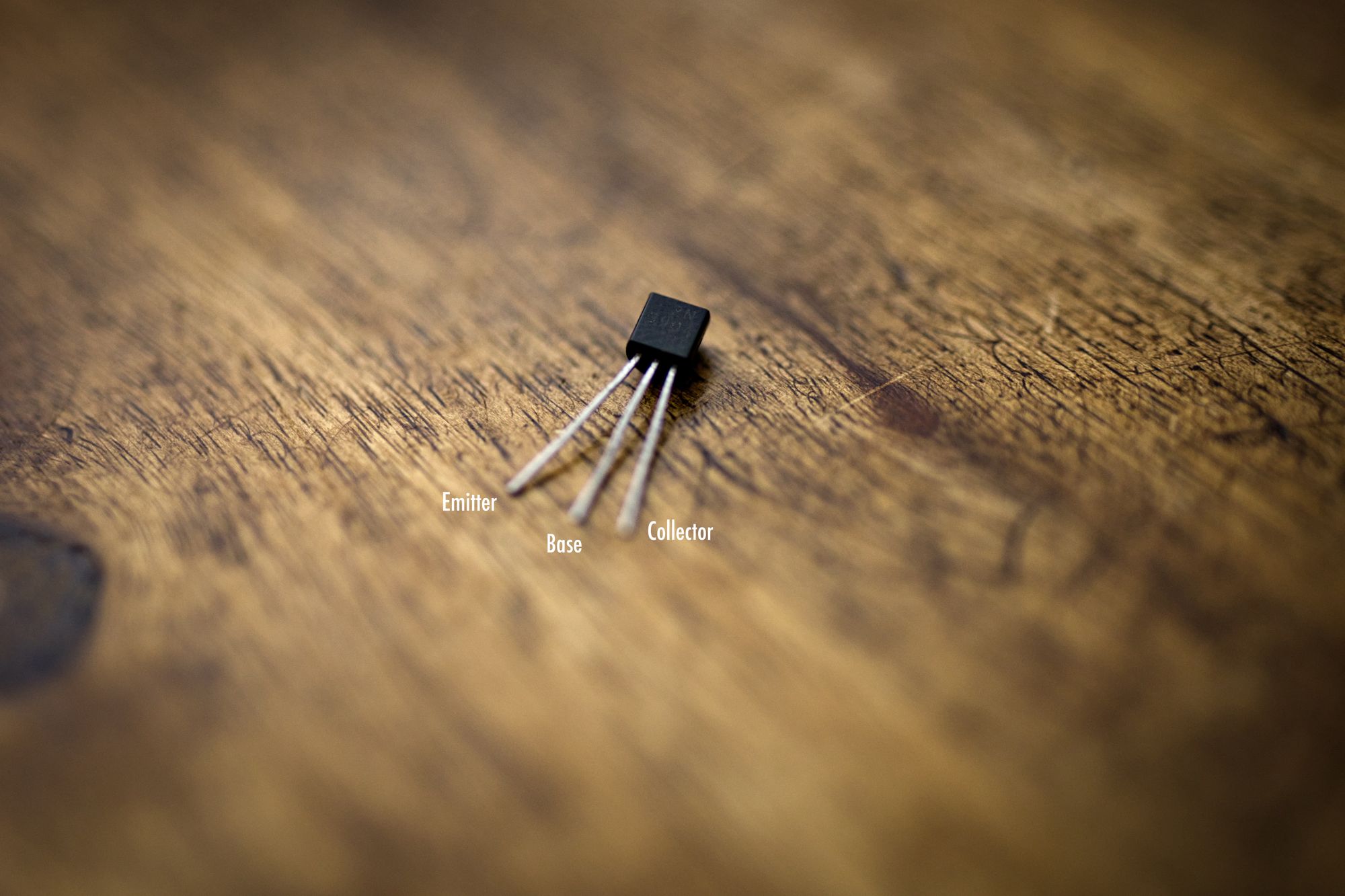
Lucky us, the temperature sensor used in these machines is a very easy thing to build. We just need a NPN transistor: the one HP uses is a 2N3904, but any NPN trt should do, like a BC547 or a 2N2222. I was lucky enough to keep a couple of 2N3904 from my university days, so I just used one of those.
You need to short the base and the collector together, as they will become the positive of the sensor. Then the emitter will be the negative pin. This is how mine looks like:
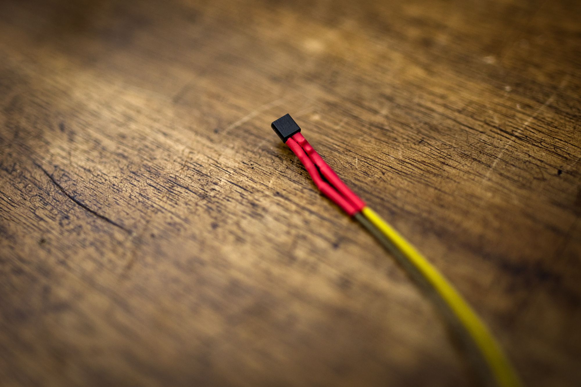
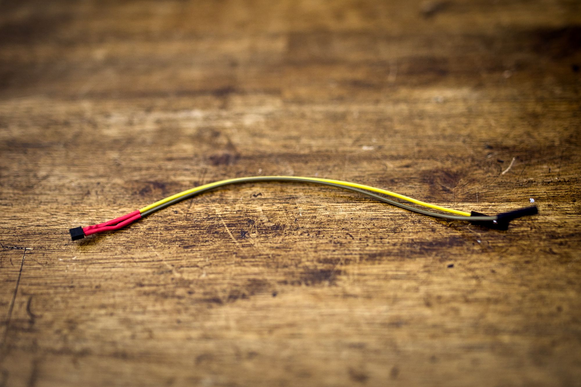
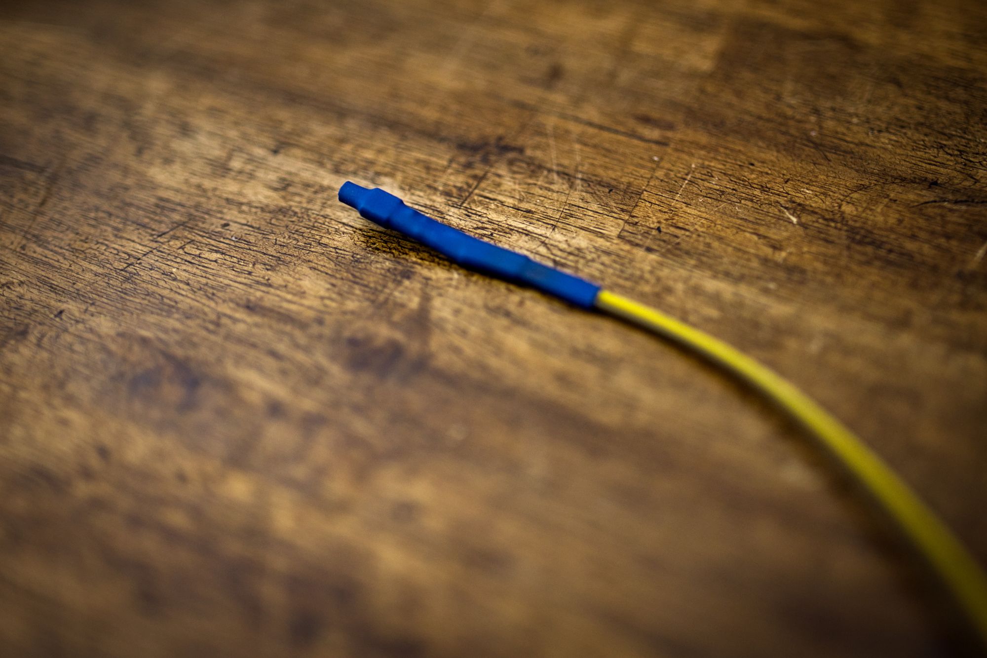
I wrapped it in thermo retractable sleeve to try to mimic as much as possible the conditions of the original cable by HP, and also to avoid possible shortcuts with the case or other parts.
Then, you need to connect the negative to the pin 12 of the P5 connector in the motherboard, and the positive to the pin 11. Is that easy.
Other Perks
When we put 1.25V in the PSID pin, and we feed all the tach pins with valid tachometer signals, the board will still complain about two things:
- No audio connector
- No front usb connector
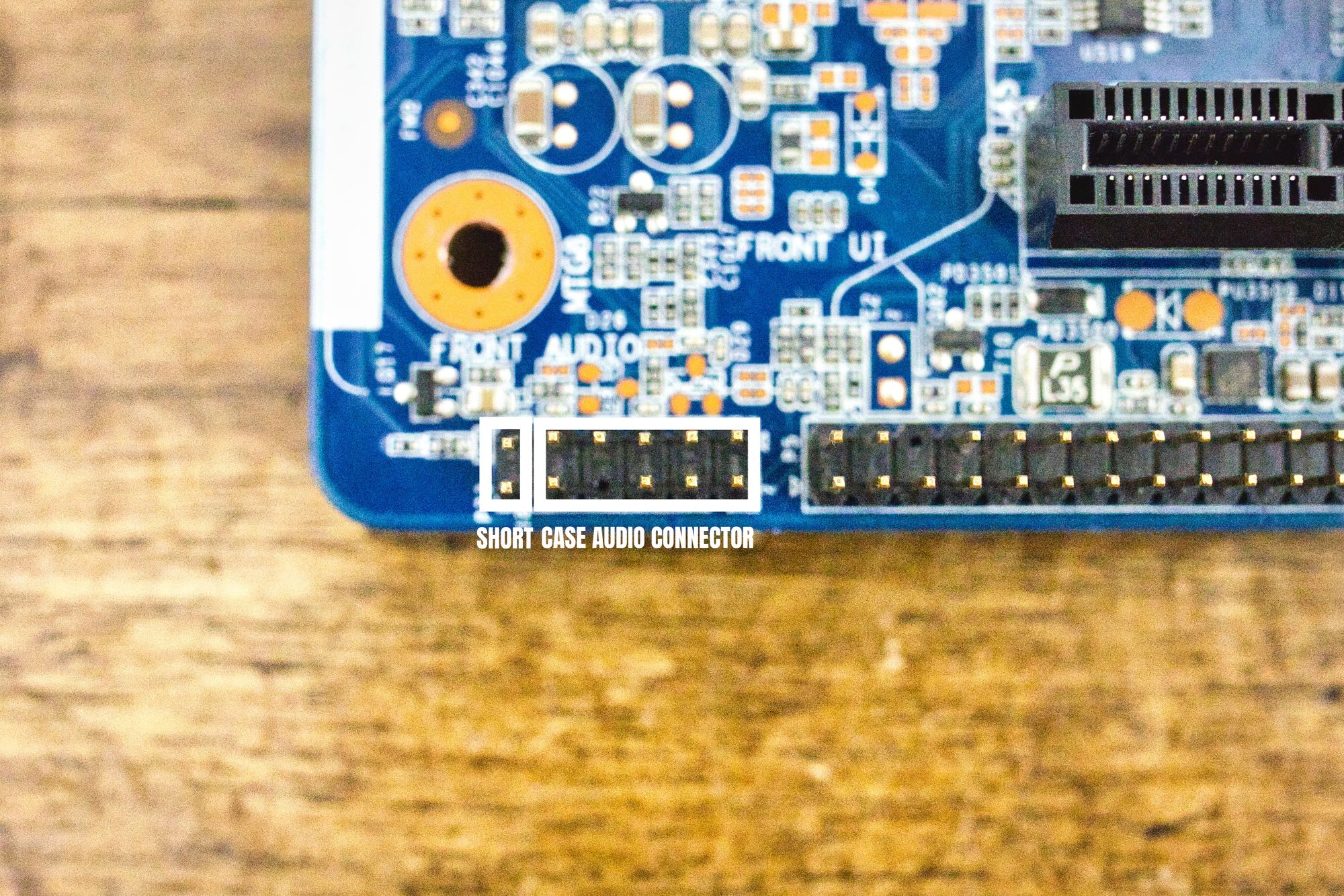
The first one is easily solvable: we can disable the audio connector in the bios and the error will go away. Of course we will not have onboard audio, but that is not a problem for me as I will be using an external usb audio interface. If we need to keep the onboard audio, we can just plug the case audio connector at the right part of the board connector, and short the two remaining pins using a jumper.
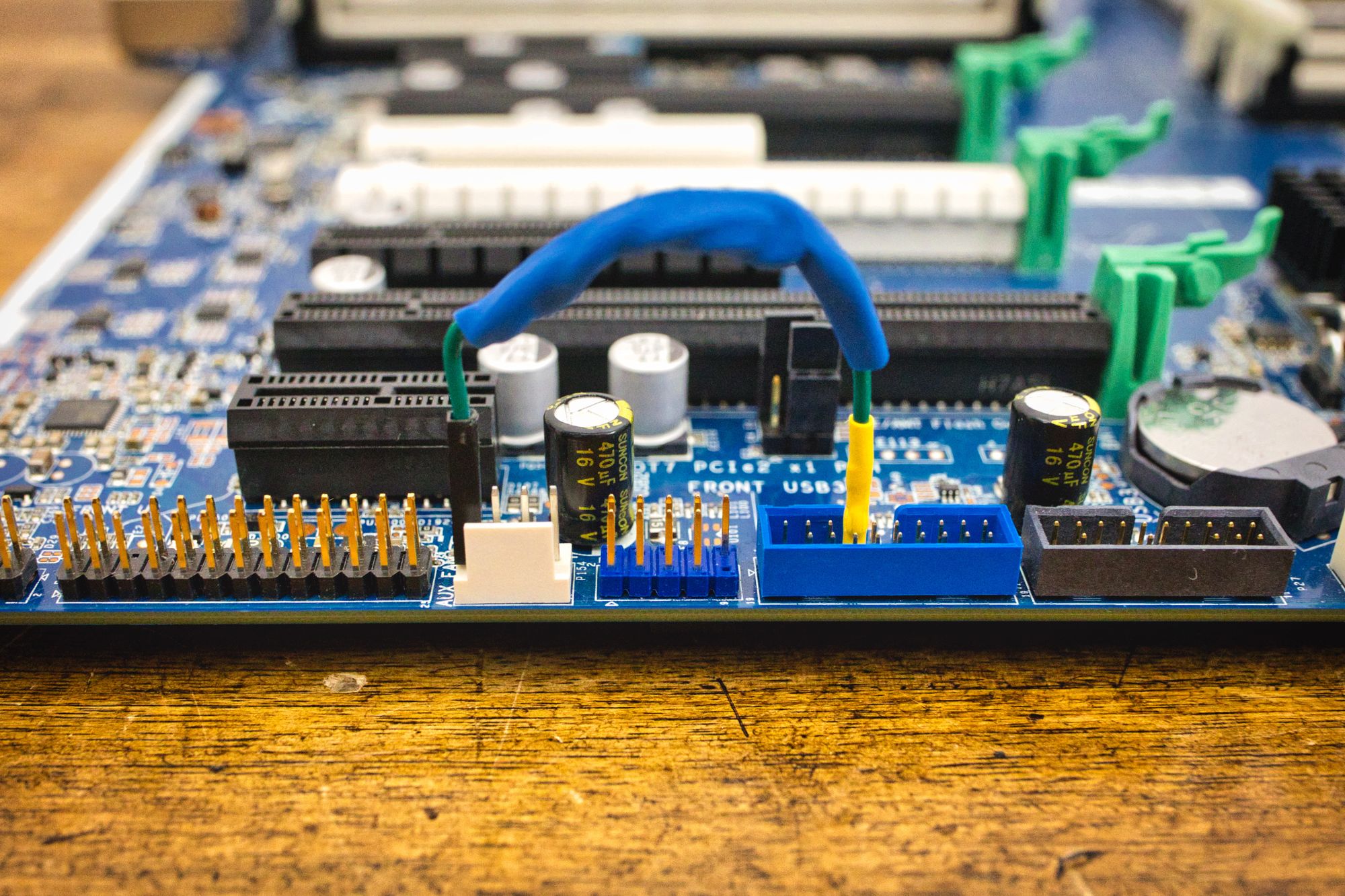
The missing front usb connector will be more cumbersome. We can disable the front usb ports in the bios, but the error will persist, as the board is actively looking for that cable. Also, shorting the pin 10 to ground in the USB3 blue board connector as people suggest across the internet will not do. But I found something weird in that connector: the pin number 4 should be ground, but it is not shorted to ground in the board. When we power up the system and we measure the voltage in that pin, we find out it is 3.3V, so the board is using it as a sensing pin. Nice. We short that pin to ground, and the error goes away.
Perfect. With all these things done, the board will boot up nicely with no errors at POST. We can now focus in connecting the power supply to the board.
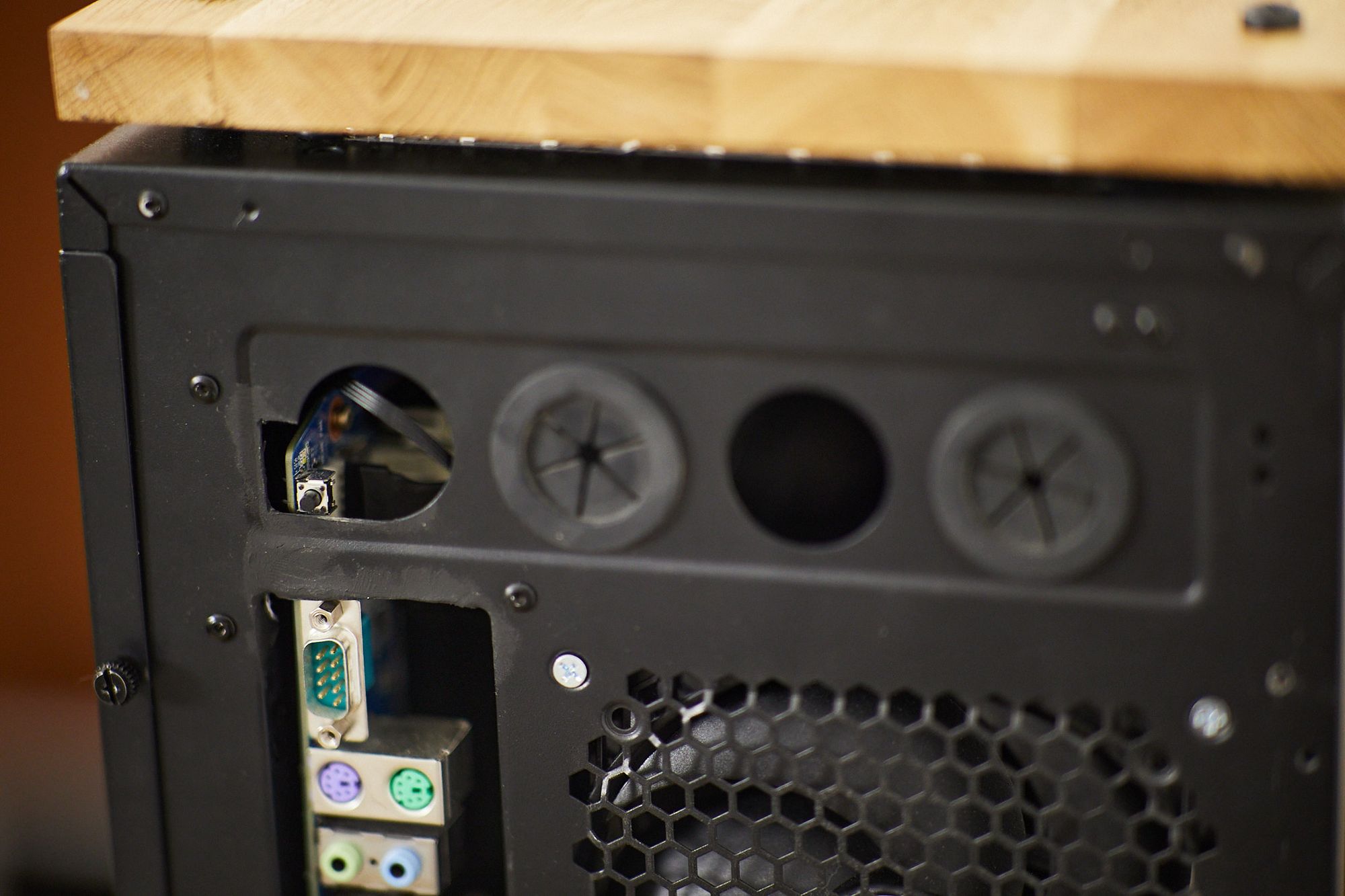
Just a little note here: to power up the system you can use the little black button at the back of the case, or just use a push button shorting the pins 7 and 8 in the P5 connector.
2. The Power Supply
As we have seen, we need to build cables to connect the board with the power supply. Luckily, while all power connectors are proprietary, they are all subset of the 24 ATX connector. So we can just buy ATX extension cables and cut out the parts we don't need.
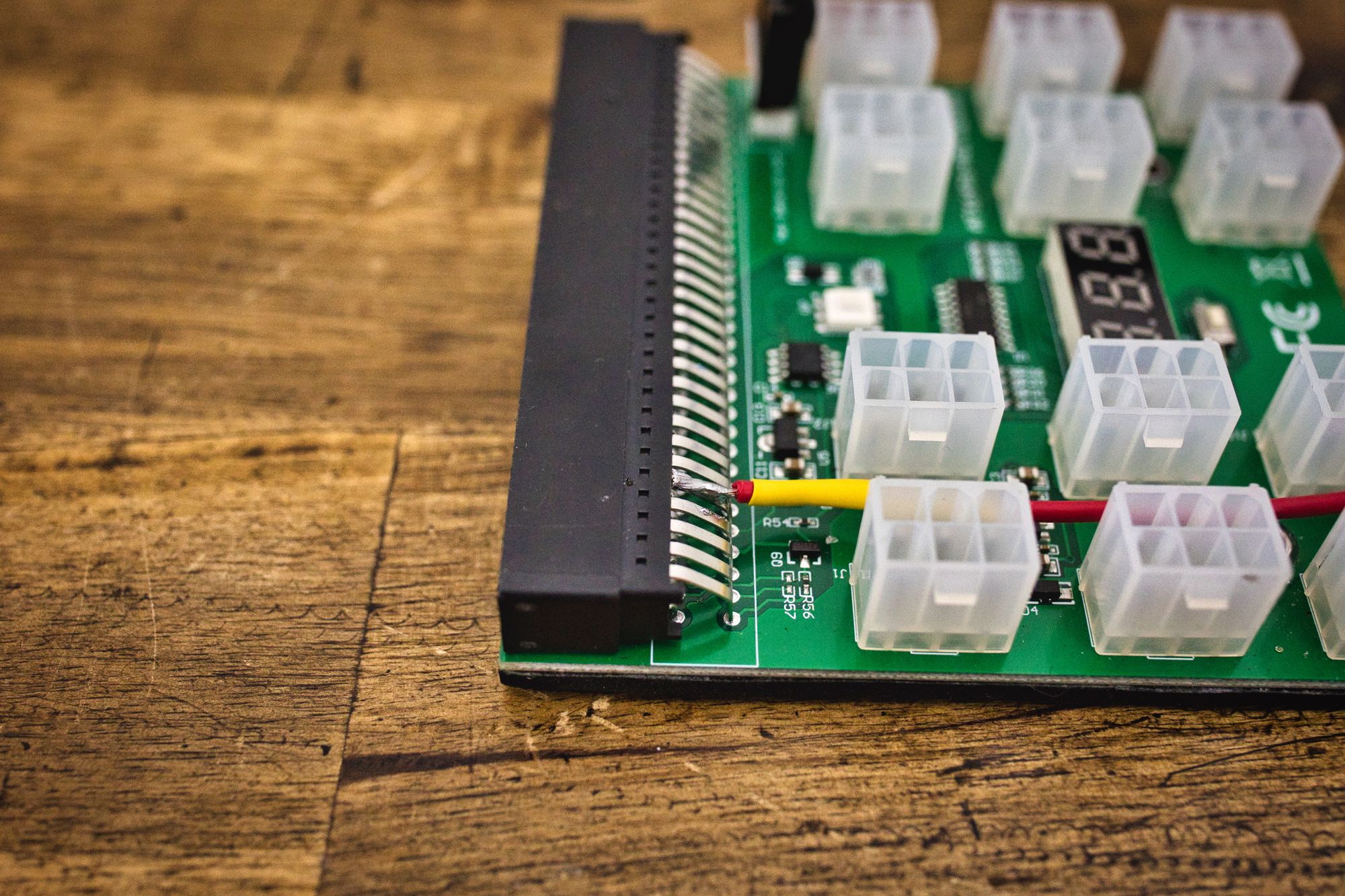
After all that work, I ended up with this:
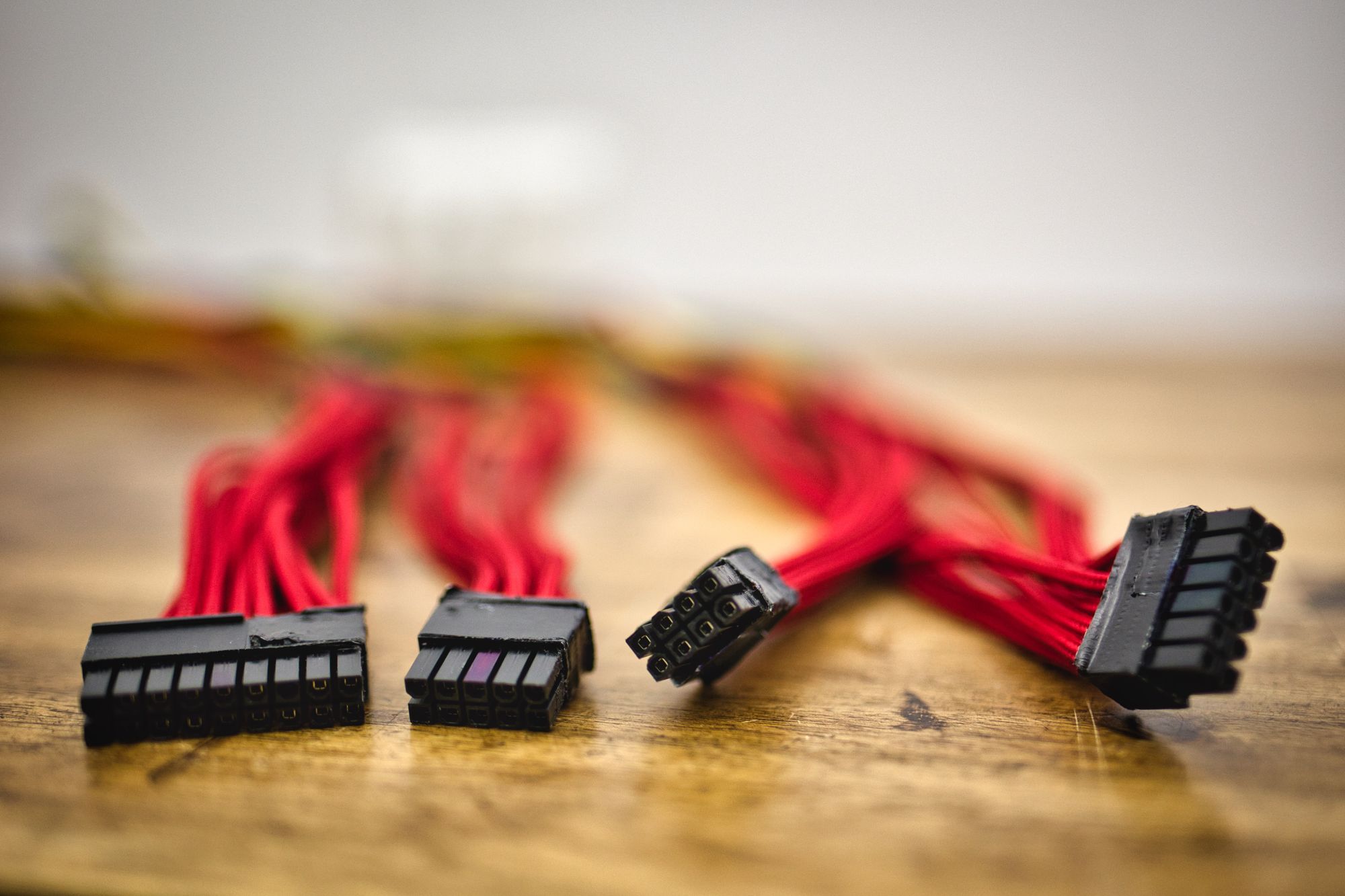
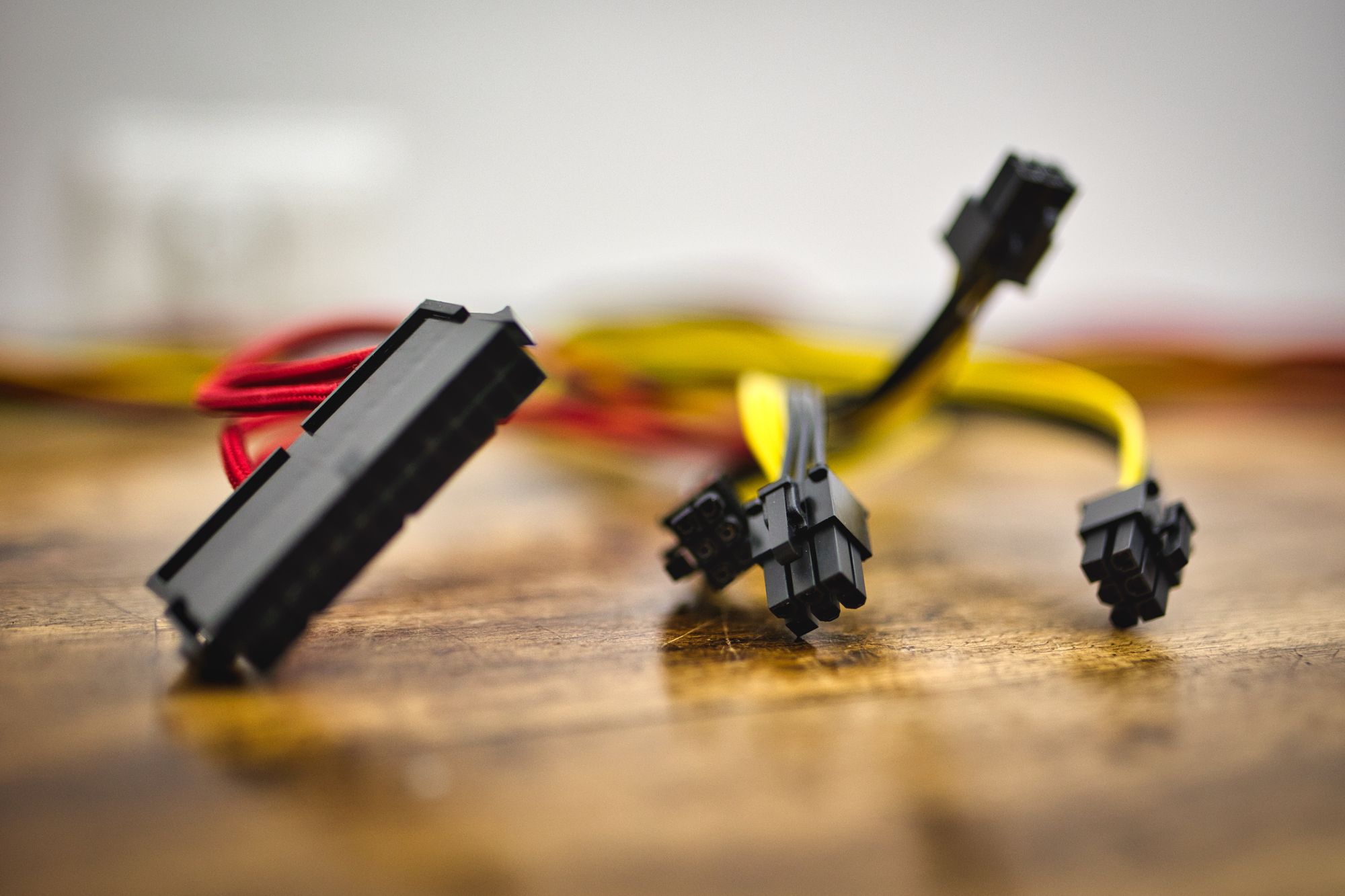
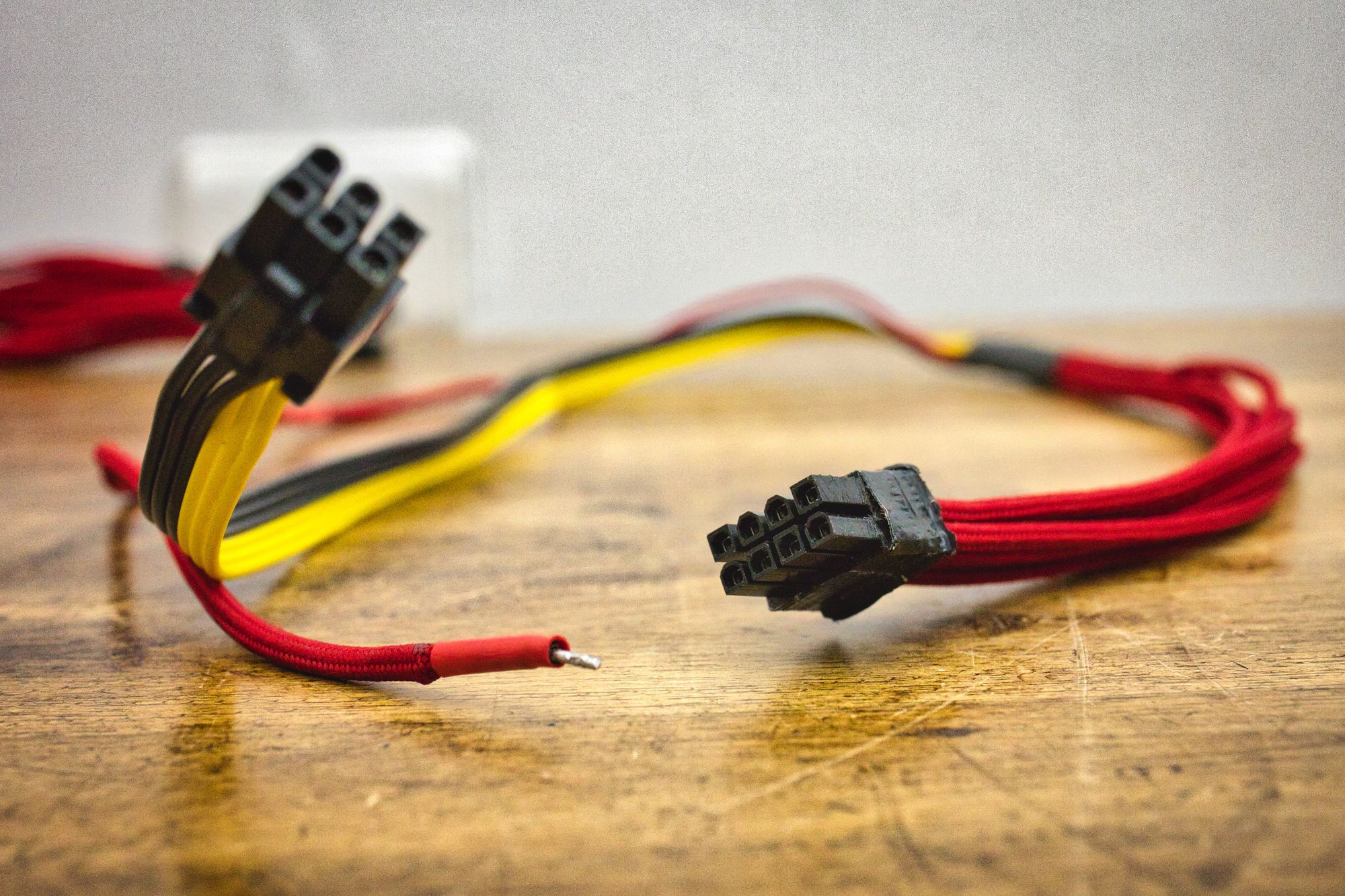
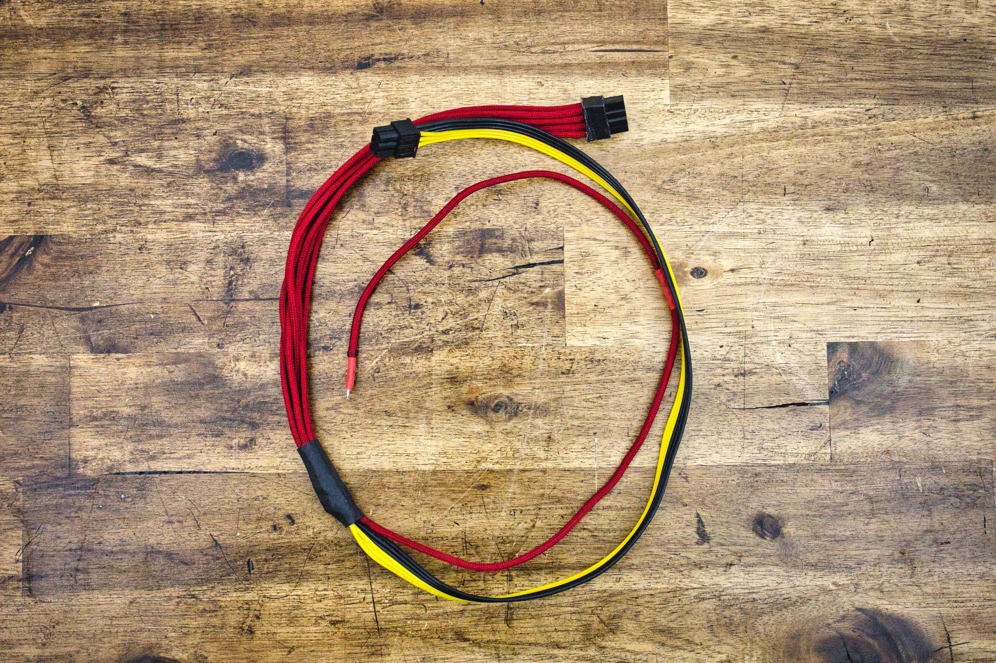
In the pictures we can see all the connectors used by the board, and a close up of the other endings of those cables: I've used GPU power connectors to end them, and you will see why in a minute. In the last picture we can also see one of the cables that need that additional 5V signal, and how I solved that.
We need to decide what power supply to use. It has to be high power, at least 600W or 700W, and we need it to have powerful enough 12V rails to accommodate the demands of the board. Modularity will help a lot. We could choose any modular 1KW power supply in the market but... knowing the board is 12V only, we can do some magic here.
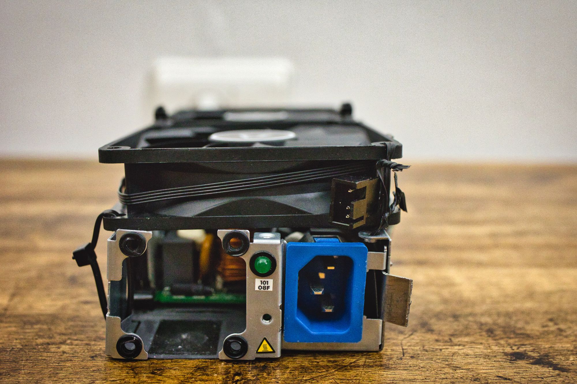
This is the power supply I have decided to use:
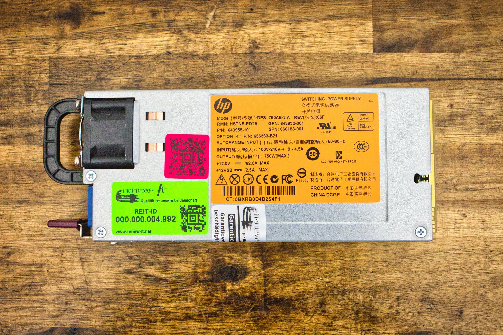
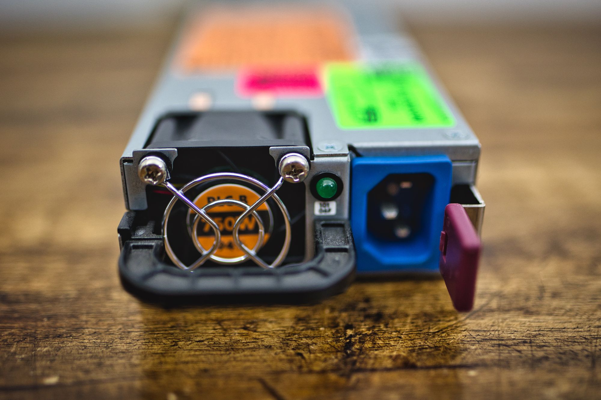
This is a 750W platinum plus HP server power supply. It has only one 12V rail (so we can connect all 12V connectors in the motherboard to the same rail), with a 12VSB capable of 2.5A of current, and it is dirt cheap in eBay. I bought three of them for 30 euros. 10 euros each. Crazy. I think I know why these PSUs are very popular along miners. They are stable, powerful, efficient and cheap. They have it all.
The only problem we have with this PSU is, of course, the noise. These are made to be used in professional environments, racked up with the servers they belong to, and quite far of human ears. They are incredibly loud when they ramp up, with a whining noise very upsetting and disturbing, at least for me. So we need to take care of that.
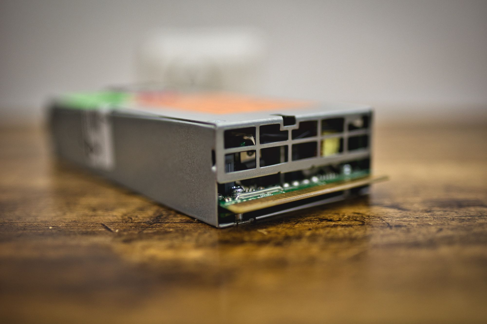
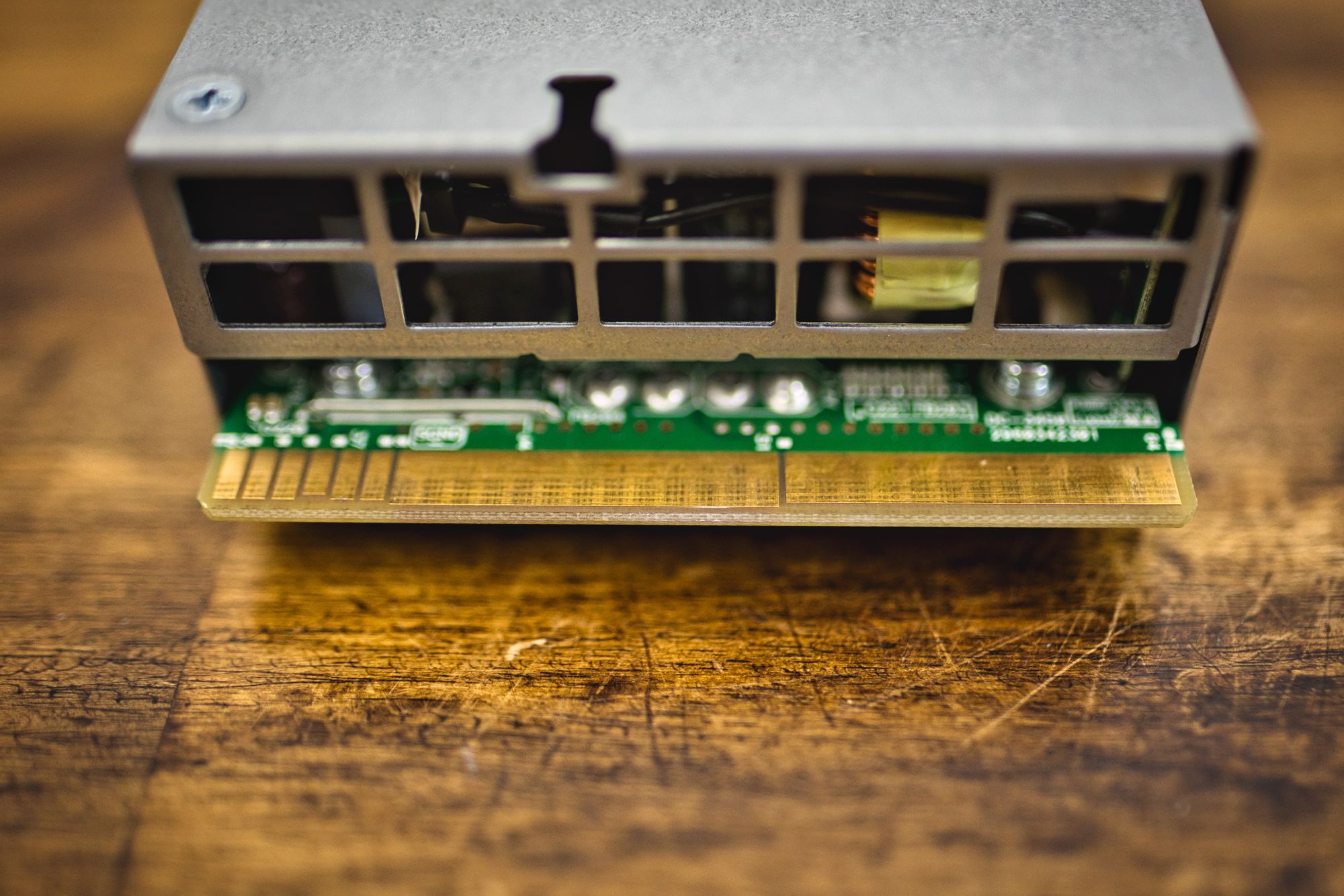
We are going to remove the lid of the power supply, in order to take out the fan. When we do that, the thing will refuse to start, powering off immediately when it detects no fan connected. To prevent it from doing that, we are going to connect a square signal generator to the tach pin in the fan connector. The frequency is going to be 600Hz, and the voltage peak to peak is going to be 12V.
Doing this, the power supply will believe the fan is connected and spinning, so it will not power off. But of course it will lack cooling and it will overheat pretty fast. To fix that, we are going to add two 90mm fans at the top of the unit (remember the lid is off), which will be controlled with the PWM signal the original fan would be using. That way the power supply will control the speed of the fans, increasing it if needed.
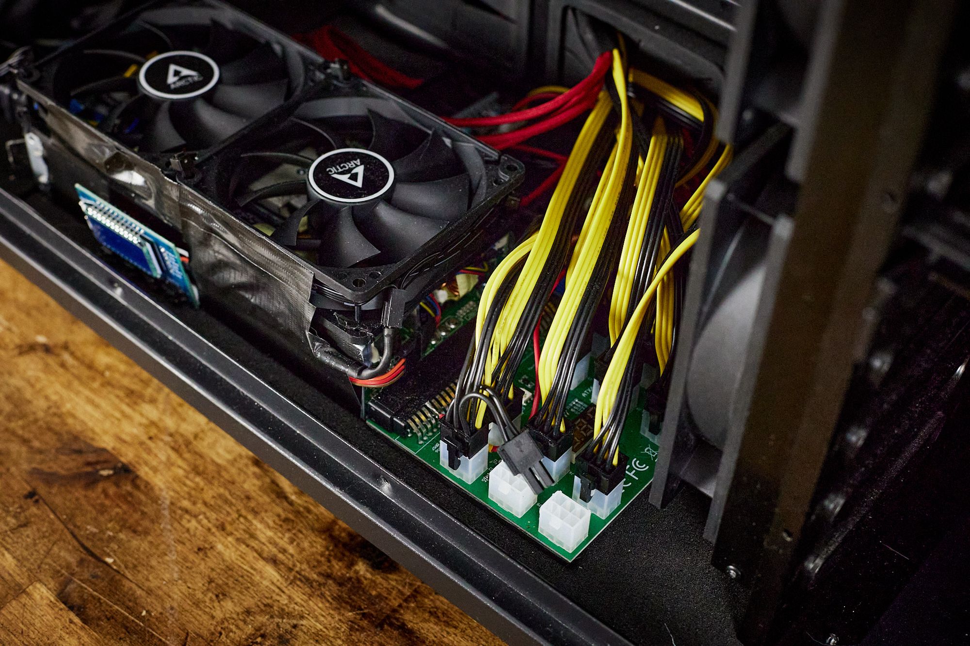
At the end of this process, I ended up with this monster:
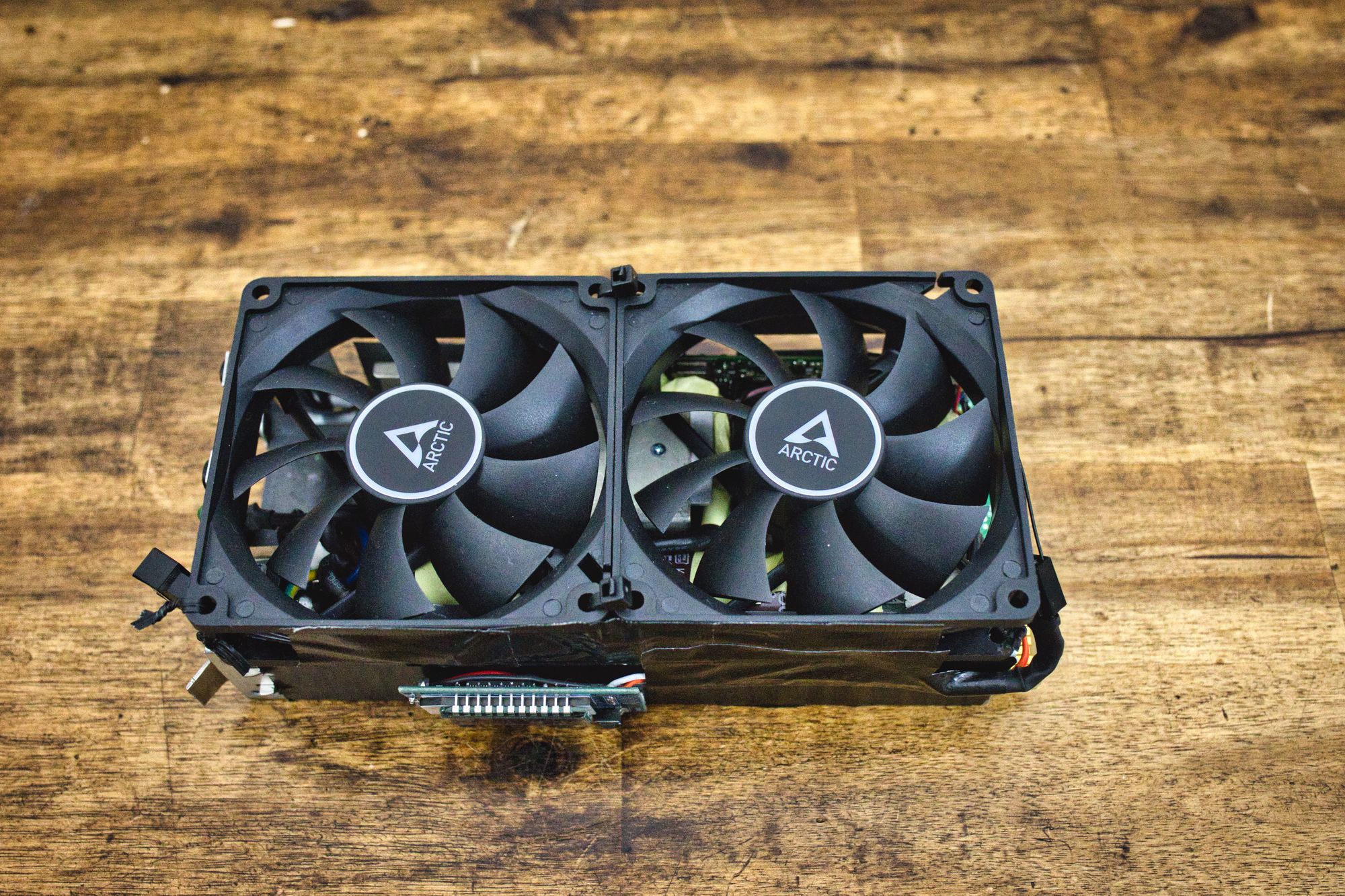
We can see the power supply with the two fans attached, and also the square signal generator we are going to use.
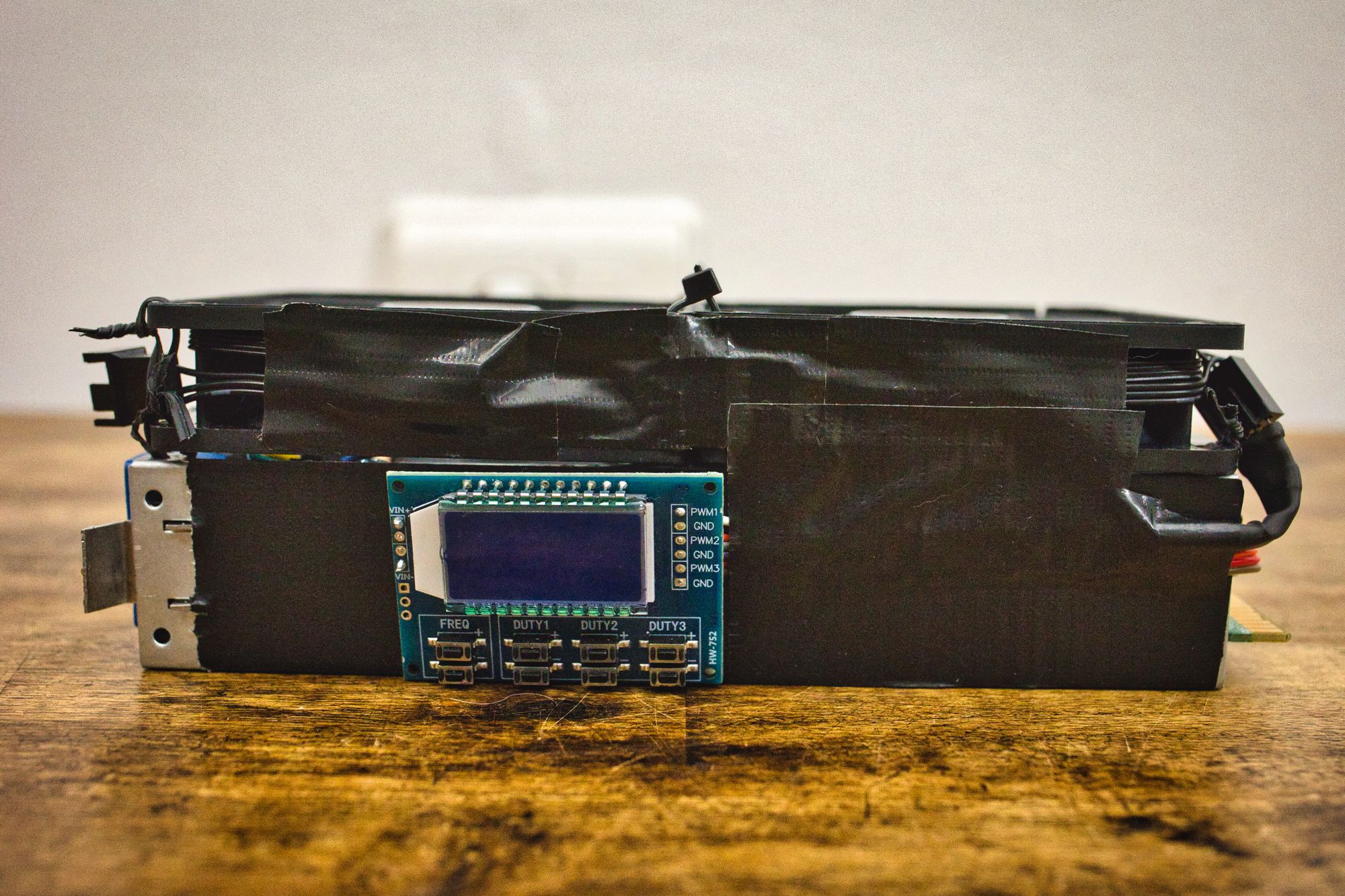
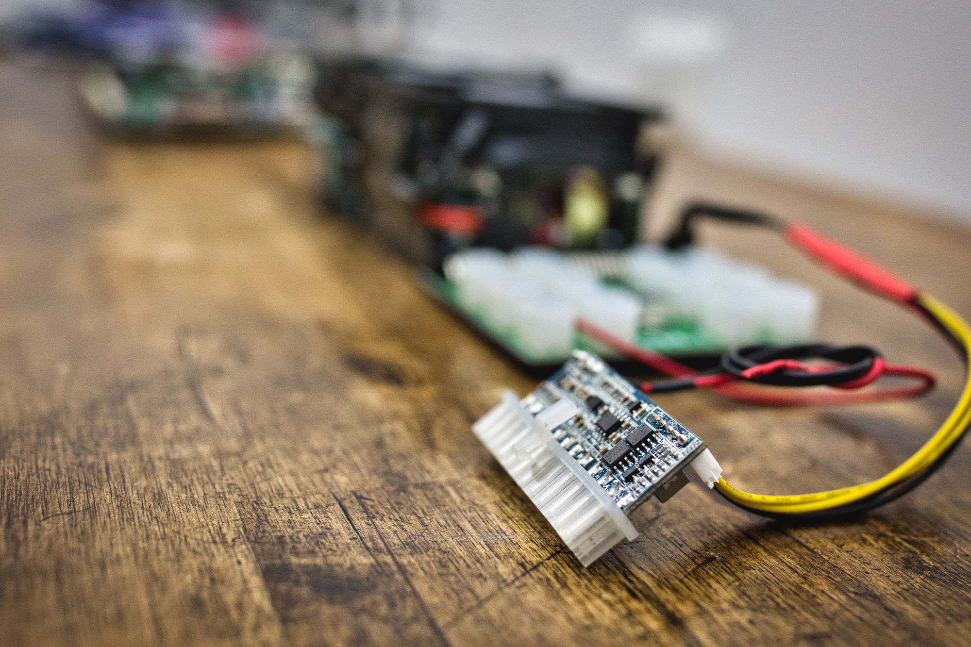
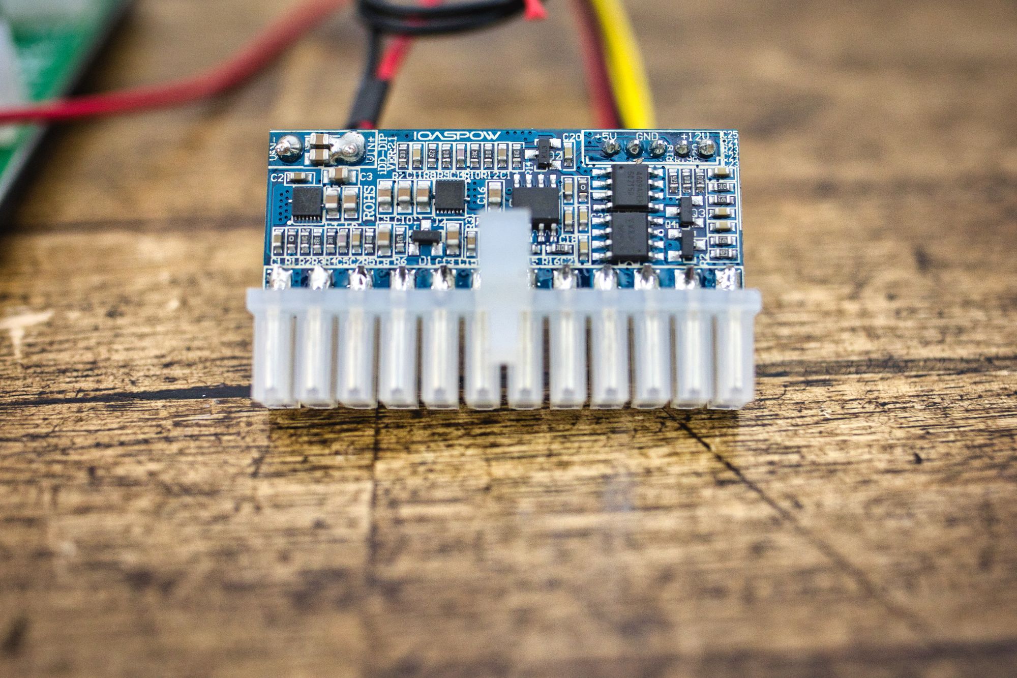
But we need to be able to power this thing on and off, and also to get those 12V into the cables in an easy way. To do it we are going to use this little board the miners will know pretty well:
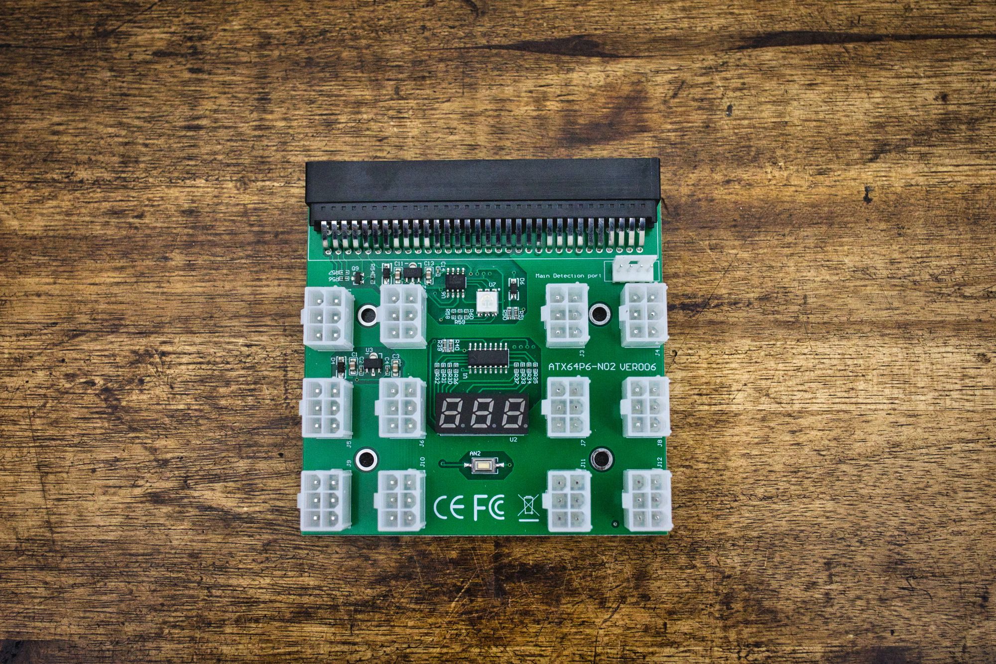
This will allow us to power up the power supply pressing the white button in the middle, and also injecting 12V in the 4 pin port in the upper part of the board. So we can also power it up electronically, which is very convenient.
Also, it will provide easy access to the 12V rail, using 6 pin GPU power connectors. We have ended all the power cables using these connectors, so we can just plug them into this board and that way carry the 12V to the main board.
But we are missing the 5VSB, the -12V and the PSON signals for the motherboard. We can not obtain them directly from the PSU we are going to use... so we need to do a little bit more magic here.
We can use a PICO PSU for that. These PSUs need 12V for power, and we can have that from the 12VSB the HP PSU gives. Then, we can connect the PSON, the -12V and the 5VSB from the PICO PSU to the motherboard, and the 12V from the PICO PSU to the 4 pin connector in the controller board for the HP power supply.
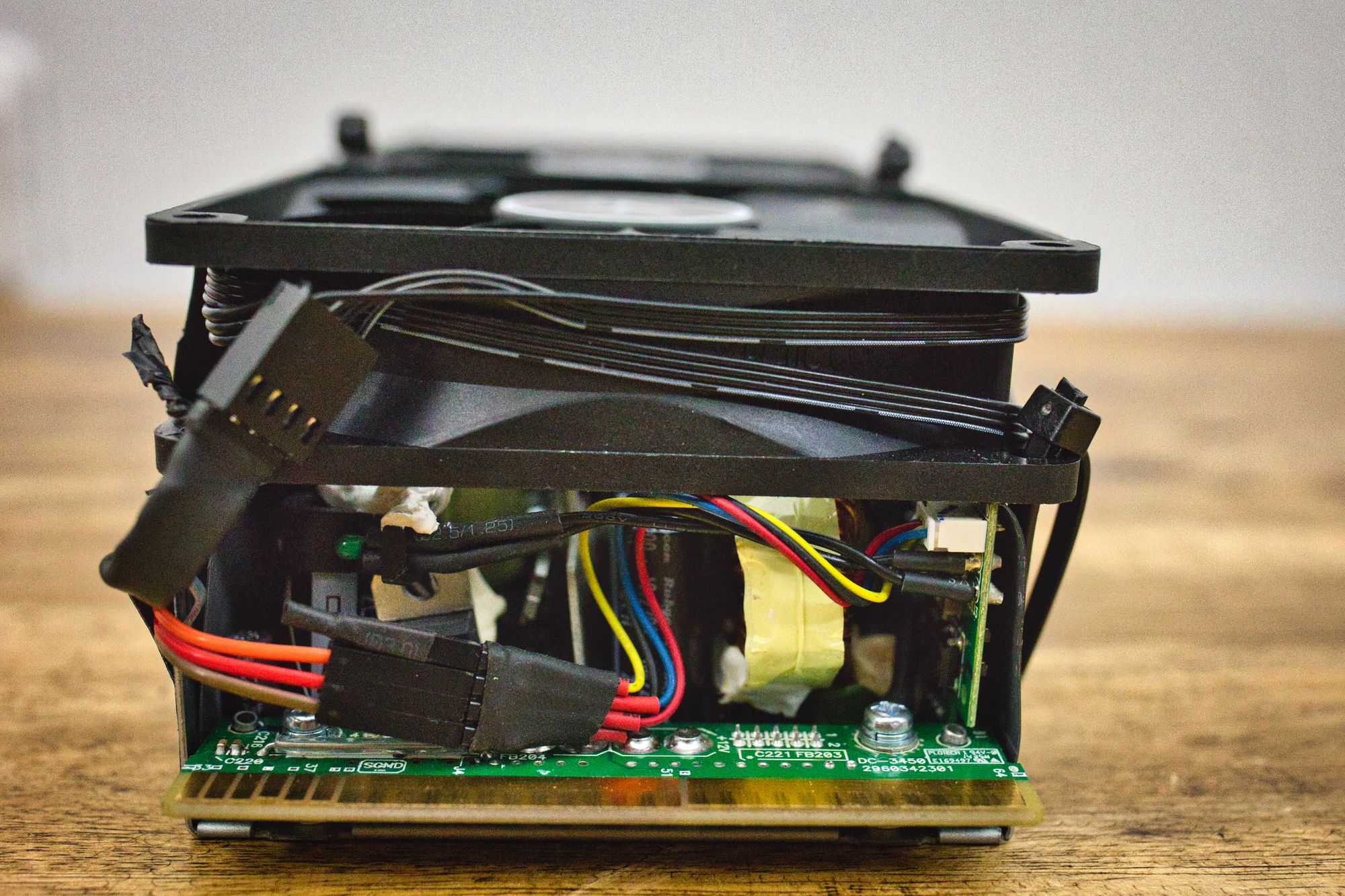
It is kind of a loop: the HP PSU provides the 12V for powering the PICO PSU with its 12VSB, then the motherboard will turn on the PICO PSU using the standard PSON pin. When powering on, the PICO PSU will turn on the controller board for the HP PSU, and when this last one turns on the motherboard will get the 12V in all power pins and it will start booting. Beautiful. All together it looks like this:
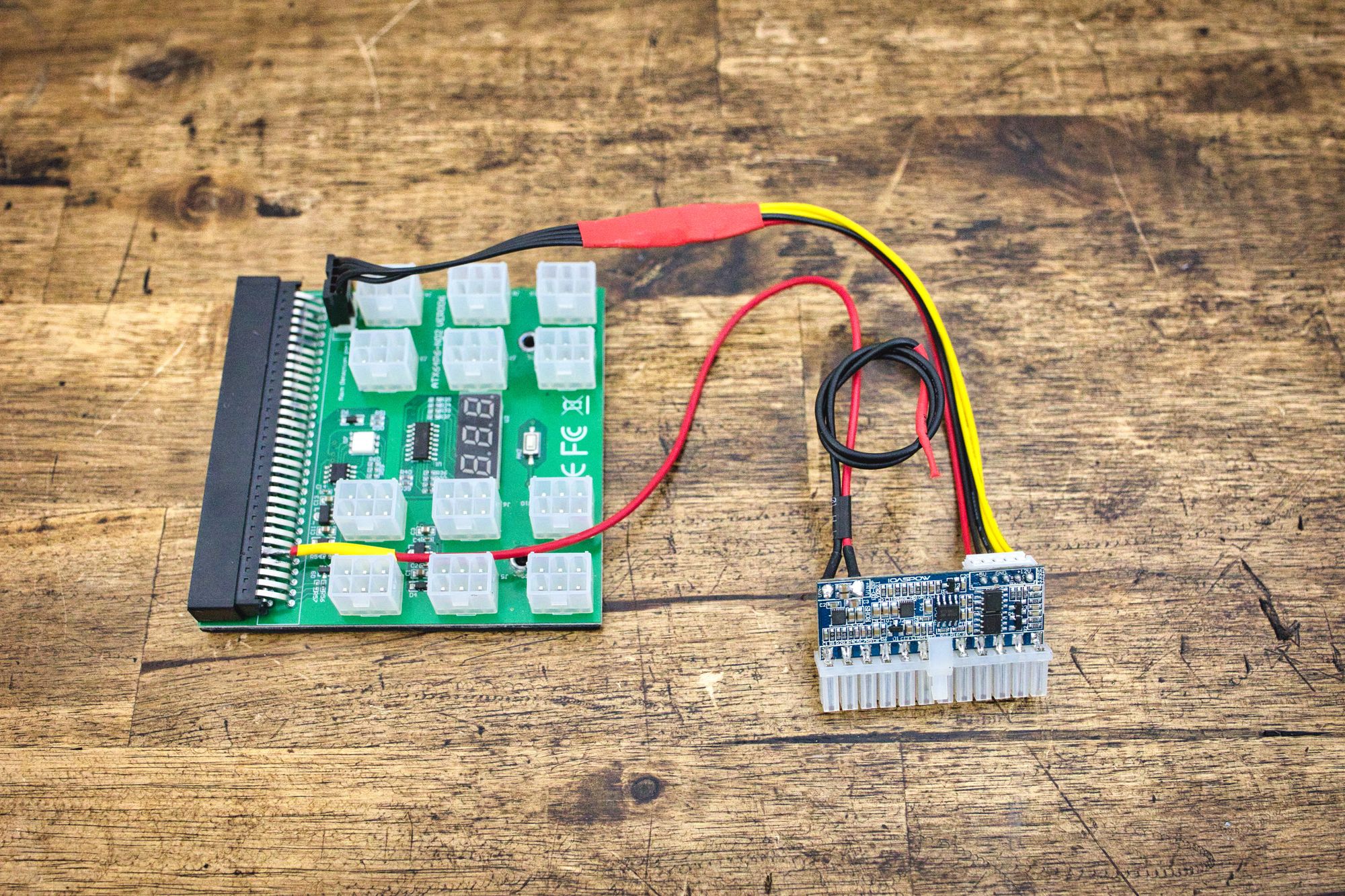
We can see how the 12VSB from the HP PSU powers up the PICO PSU, and how the PICO PSU powers up the HP PSU using the 12V upper port in the HP PSU controller board.
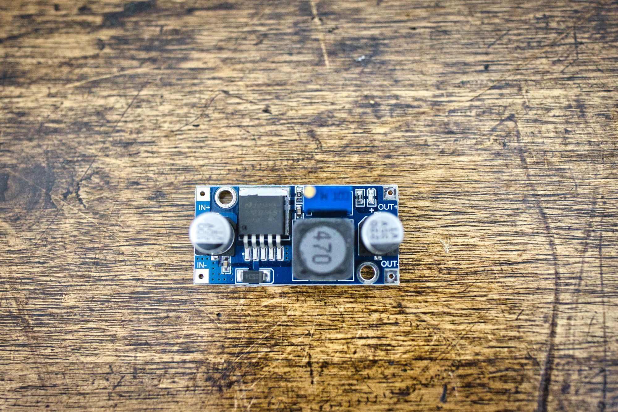
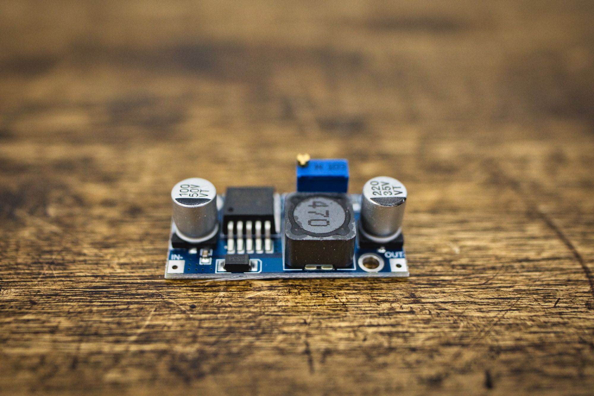
We have a little issue now, as you have surely know already: we are missing the 5V signal for the two memory power connectors. We said we were not going to use the ones the motherboard provides to keep the cables clean. Also we need 5V to power up hard drives and other peripherals. To generate this 5V signal, we are going to use a buck converter. It will take 12V from the power supply, and buck them down to 5V. Actually, we are going to use two of them: one for the memory power connectors, and another one for the peripherals:
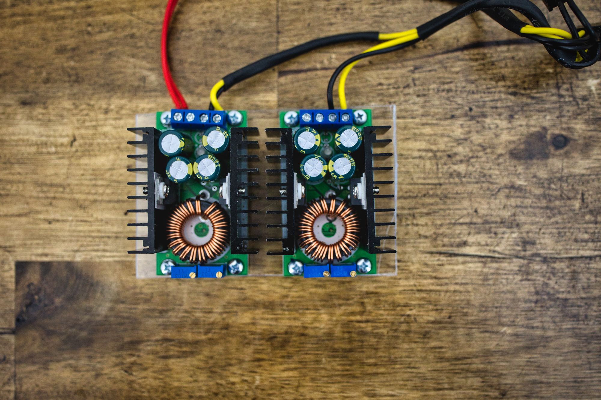
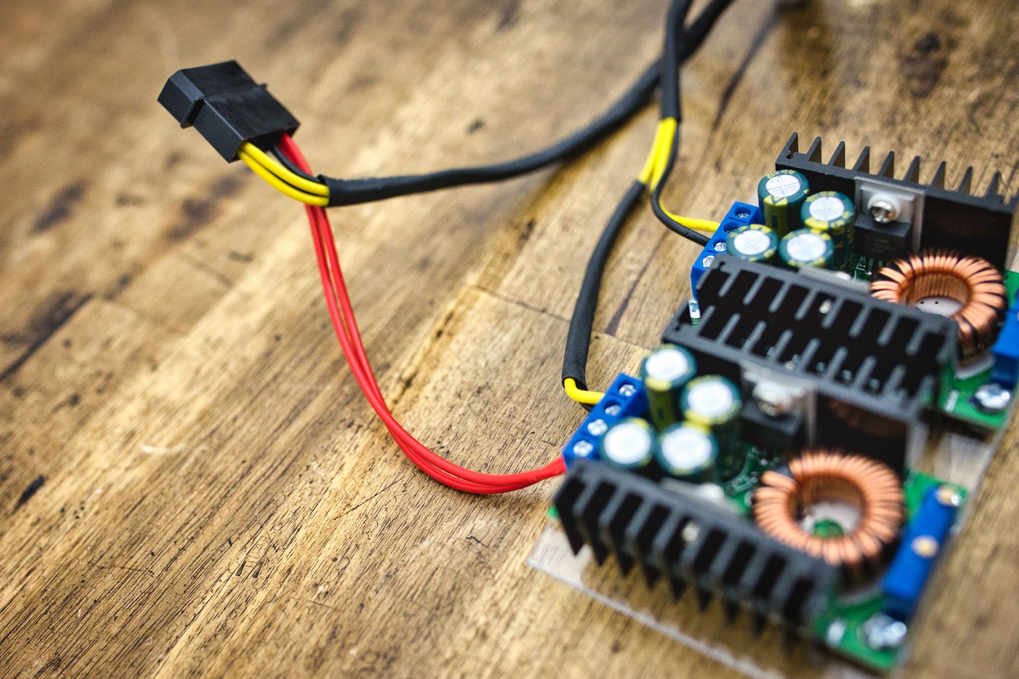
We can see how the output of left one is hooked up to a molex connector, while the output of the right one is ready to connect the pins we prepared in the memory power connectors we have seen before.
Each one of these converters will give us 10A of current, reaching 50W of power. More than enough for our hard drives.
So, we are only missing one little part in the chapter, and that is the 1.25V we need for the PSID pin in the motherboard Main Power Connector. To generate that voltage we are going to use another buck converter, just a smaller one this time. Probably we can do this with a zener or a resistor, but I did not want to complicate things even more.
The little fella looks like this:
Good. With this we have the hole power supply part covered. We should be able to power the system properly with all this stuff. Lets move to the next part then :)
3. Other Main Parts
Now we need to choose the rest of the parts we are going to use. These have come after months of scanning eBay back and forth looking for best offers and prices. Don't rush on this, take your time, you can build a very nice system for little money if you just have patience :)
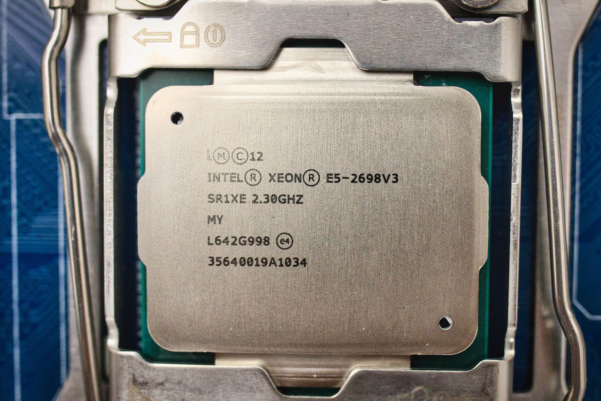
CPUs
We are going to load this motherboard with two Intel E5-2698 V3 processors. Each of them packing 16 cores and 32 threads at 2.3GHz of base clock. They will provide more than enough compute power for all I can throw at them.
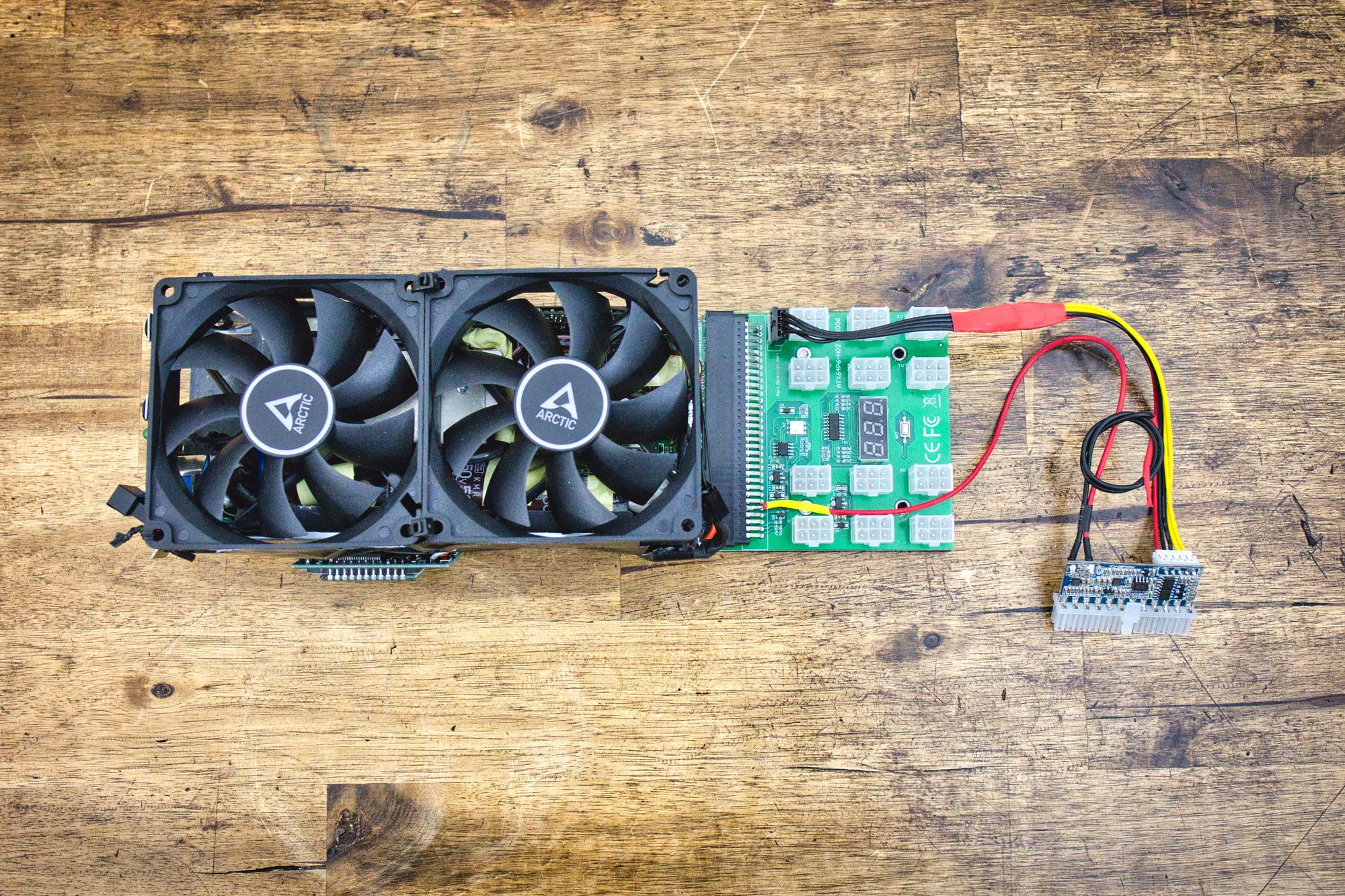
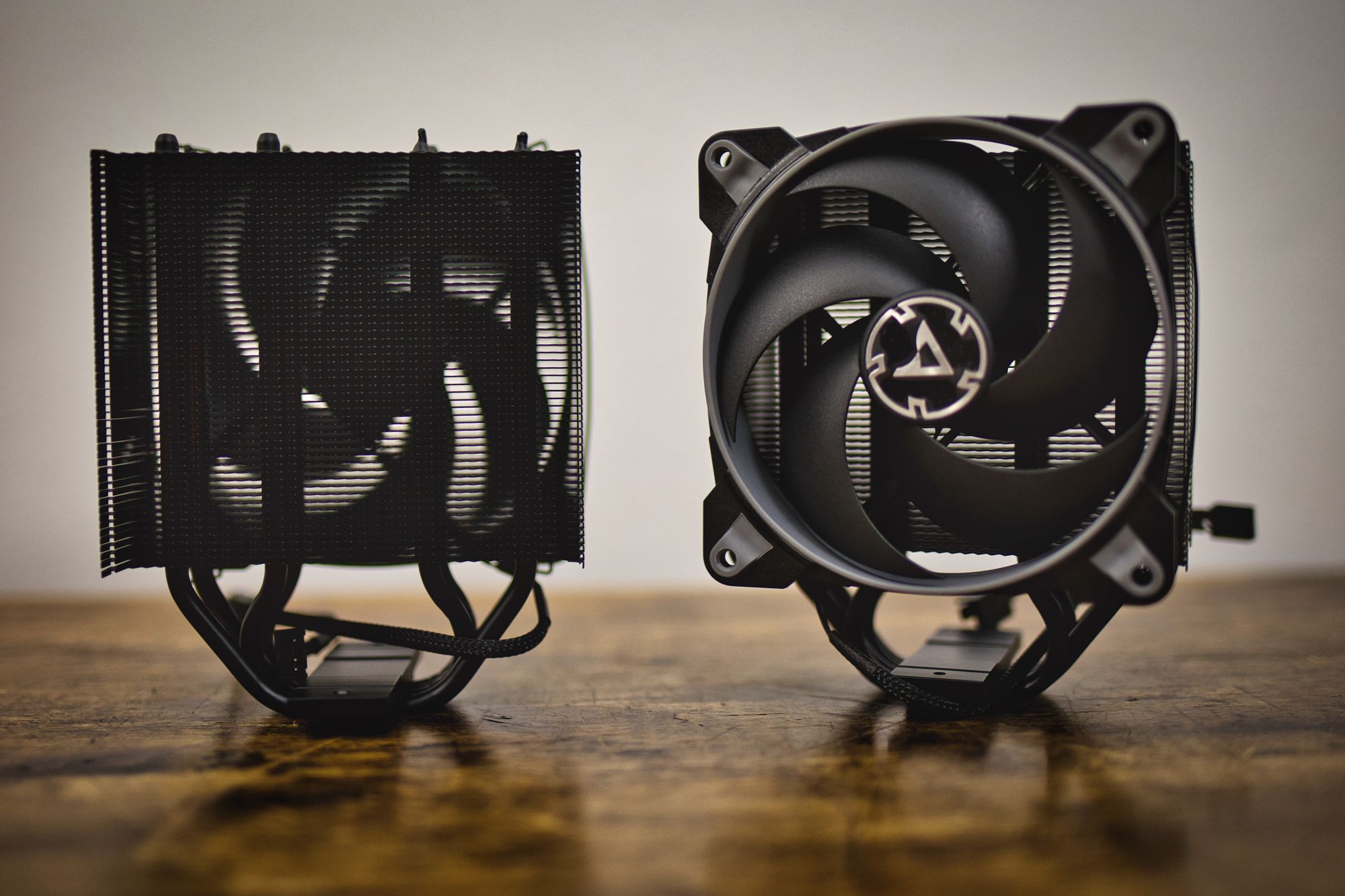
For cooling, I have chosen two Artics Freezer 34, which have nice 120mm fans which should be very quiet while providing enough cooling capabilities. Also, I believe they look awesome :)
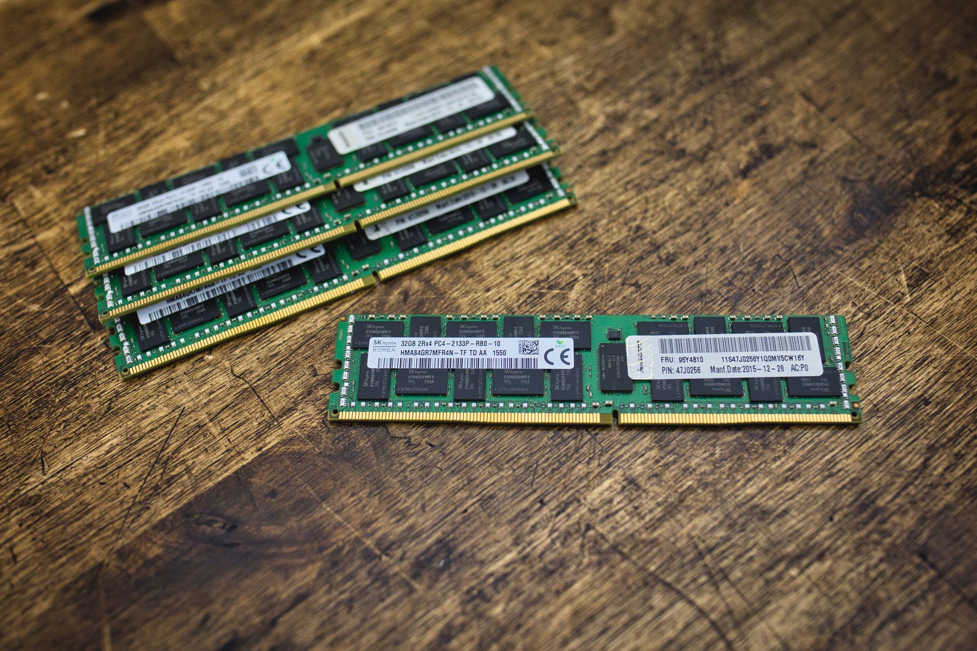
RAM
The motherboard provides 8 DDR4 modules per CPU slot. Keep in mind this is a workstation, so your normal memory sticks will not work here. You need unbuffered or registered RAM. I scored 4x 32GB modules on eBay at a very good price, adding a total of 128GB of memory for the whole system. Not bad.
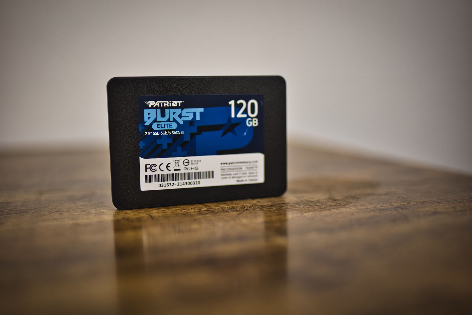
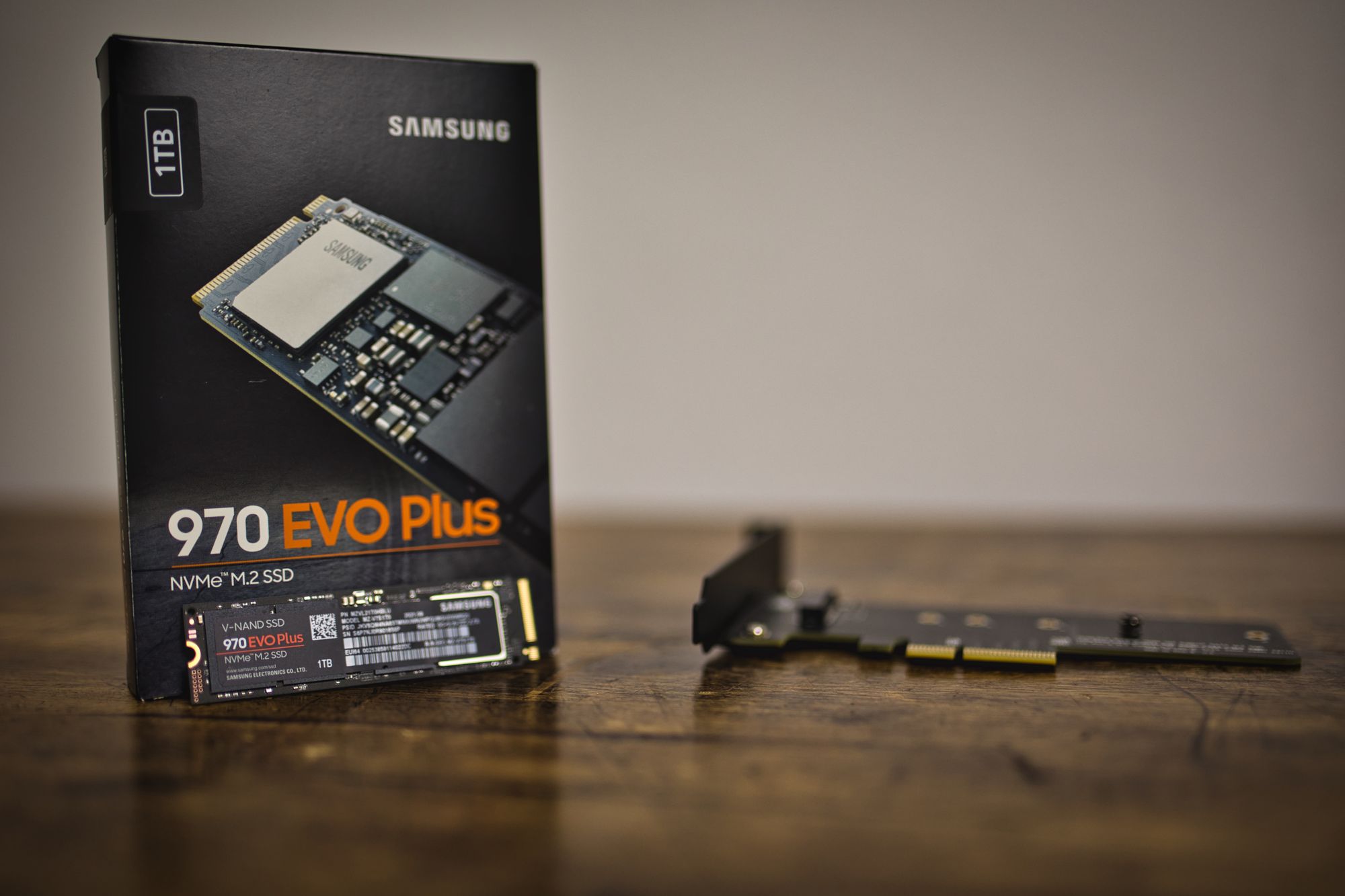
Hard Drives
For the hard drive department, Ive chosen to have a basic SSD as a boot drive, and then a premium NVME as main. For the last one, we also need a PCIE adaptor card because the board has no m.2 NVME ports.
4. The Case
The case I've chosen is the same case I chose for the Z800 project. It has been with me for a lot of time now, and it has been heavily modified over the years. The base is from a Rosewill B2-Spirit case. It is a huge case that will take any board you want to put into it, with a lot of room for GPUs, HDs, CD-ROM units, etc. It is just enormous. I think it's discontinued now, but maybe you can find it somewhere.
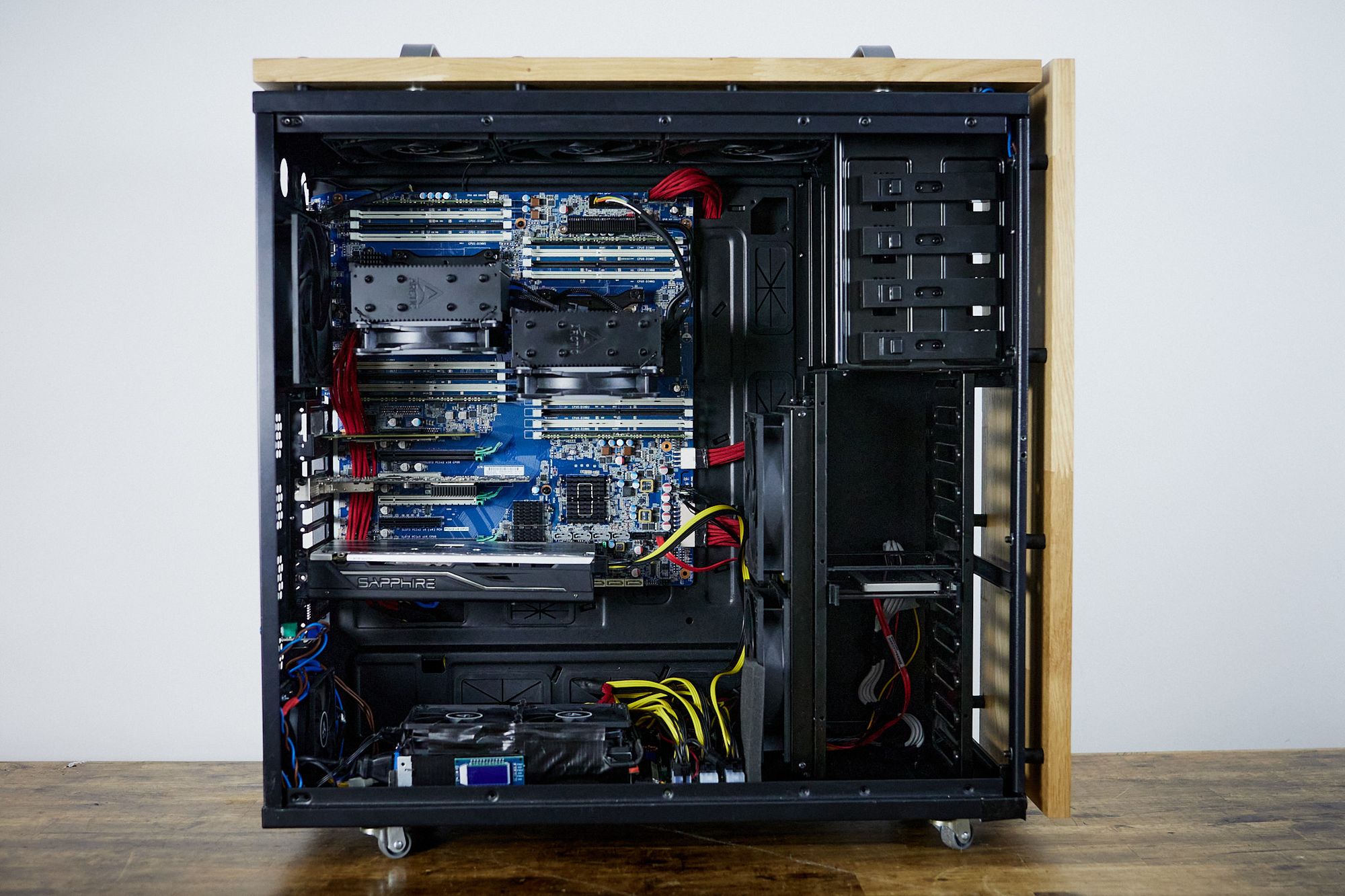
Right now, the barebones of the case look like this:
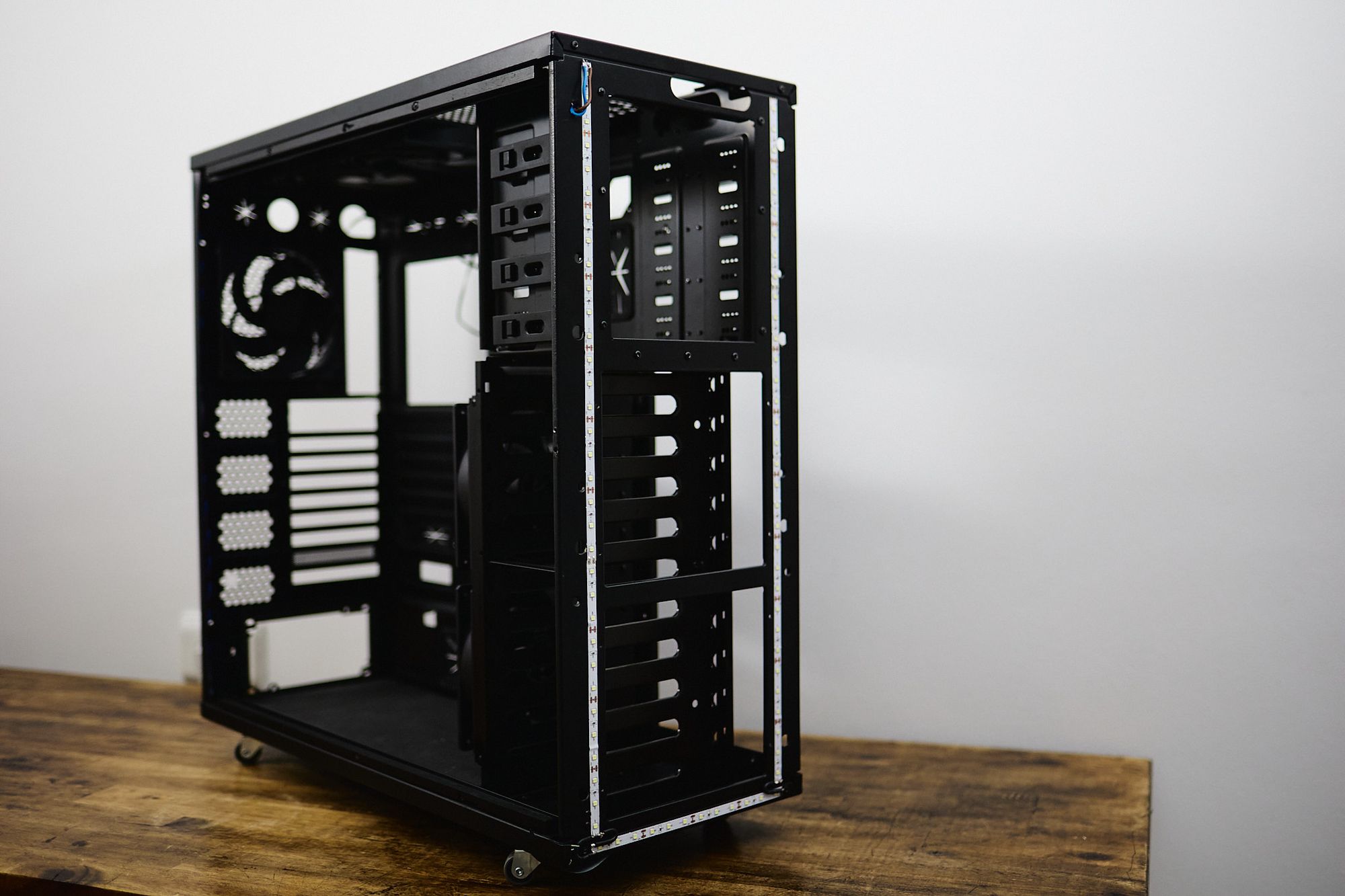
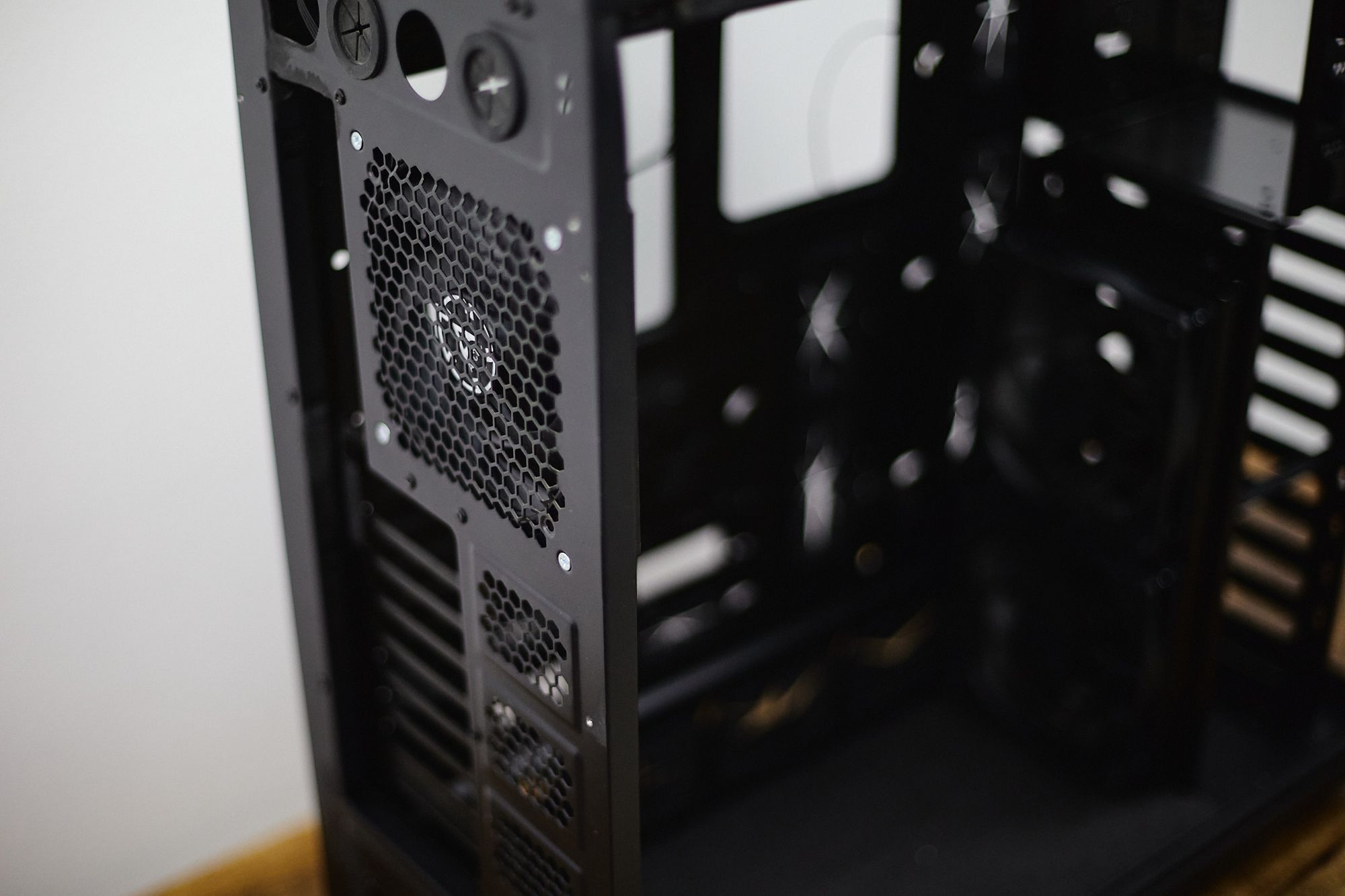
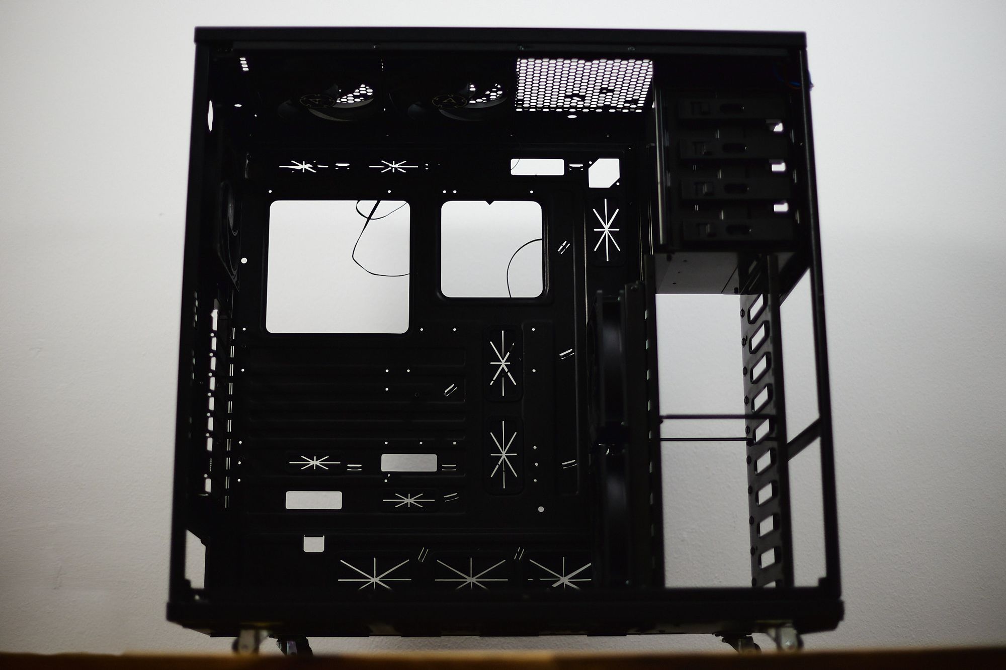
Wheels have been added, and the second drive cage removed. Ive also covered the borders with a white led strip. That way I can have a very simple led illumination that I can control using any cheap led controller. Nothing with too many colours, just white.
Ive removed the front fan cages, as I did not like them. They were producing vibrations and very annoying low hum which was very disturbing and difficult to get rid of. When I removed the cages and just placed the fans inside, the case is quite as a mouse :)
We can see the multiple fans the case accepts. 3x 140mm at the top, 2x 140 mm at the front, and 1x 140mm at the back. That is a lot of air moving, and being the fans that big, they will make sure the system is cooled properly and silently.
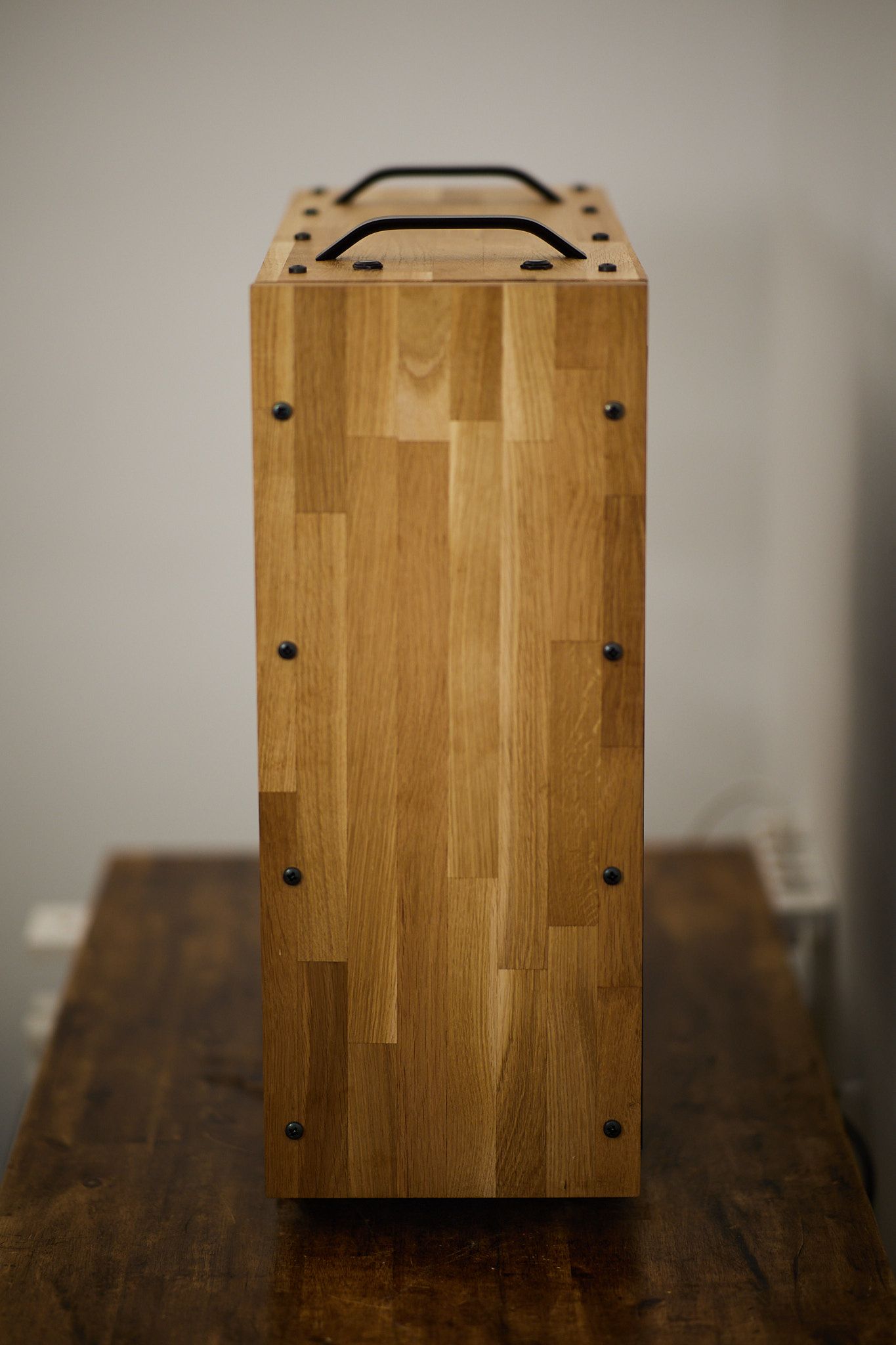
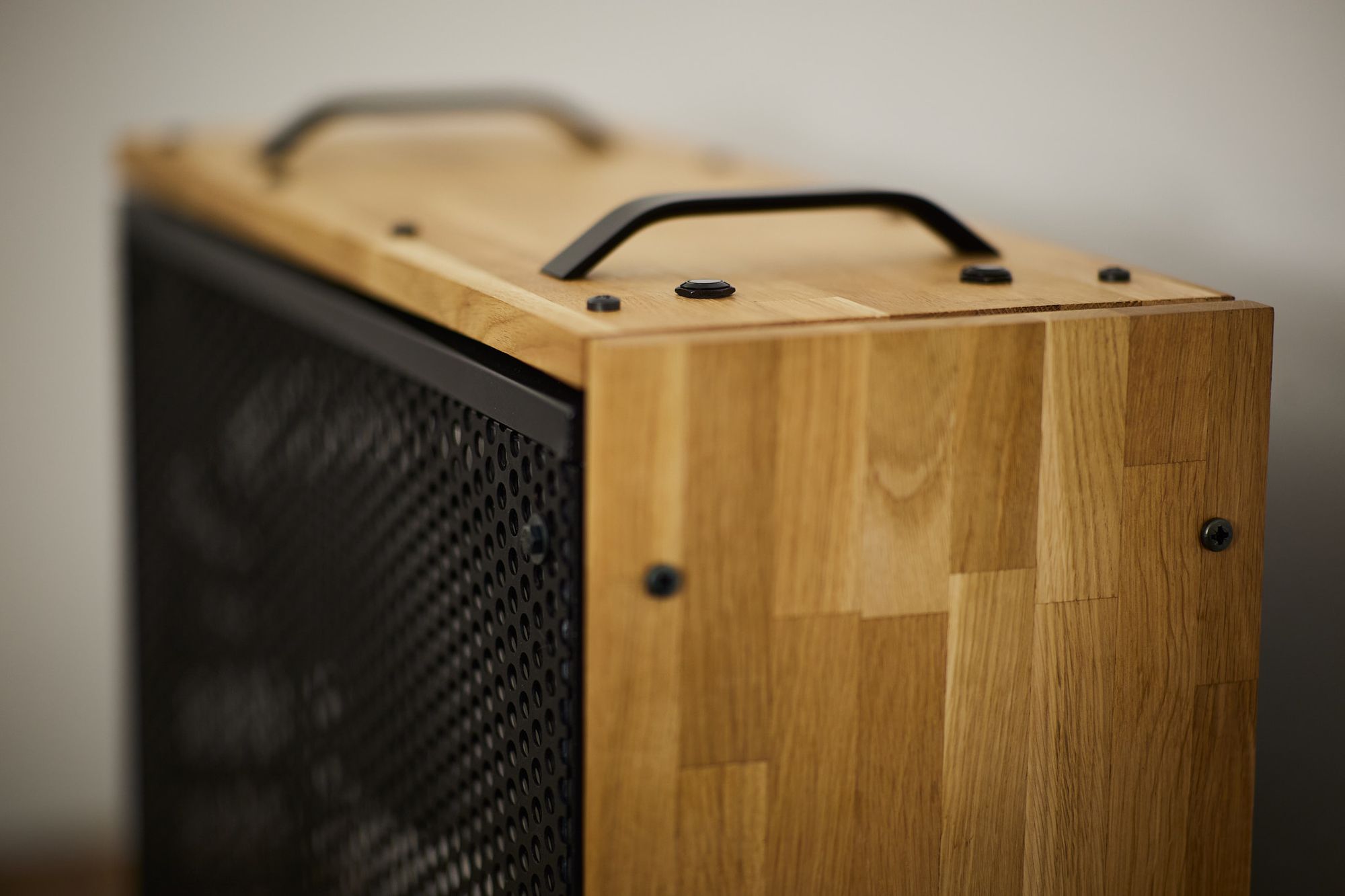
I wanted this case to look different, and I also did not like the original panels material, which was black plastic covered in that gummy soft black paint. Lots of digital prints over it, a nightmare to clean, I just hated it. So I went for a classic 2 cm thick spanish oak cuts. I used the existing holes in the chassis to accommodate the originals panels, and drill some holes in the oak to use M6 screws.
So, with everything in the case (motherboard, drives, GPU, PSU, etc) it looks like this:

Looking closely at the PSU part, it is looking not that messy, I honestly though it was going to be a lot worse):
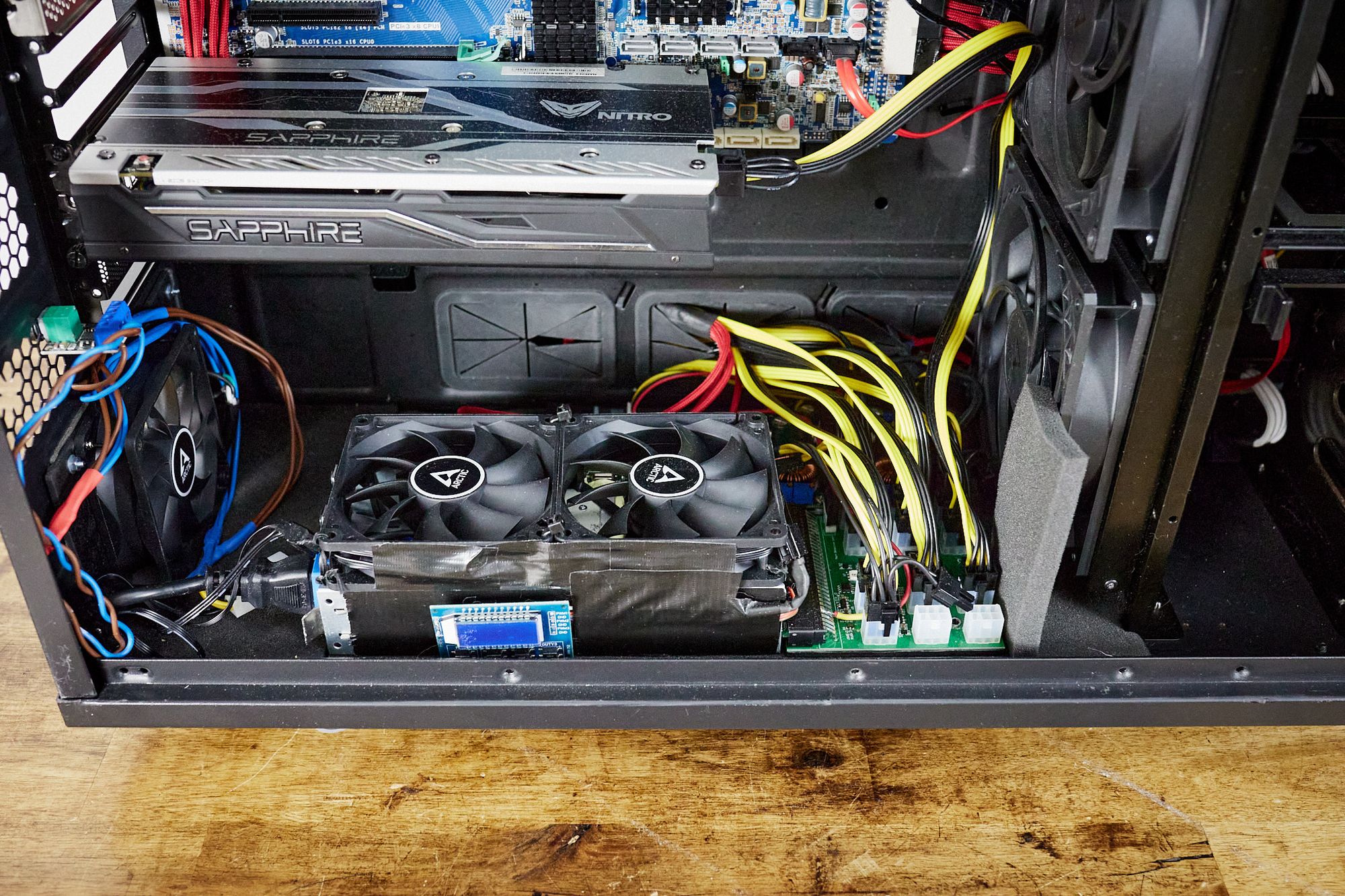
That little board you see at the top of the PSU space with all those blue wires coming in and out is a LED power controller, for being able to adjust the luminosity of the white LED strips surrounding the case we saw earlier.
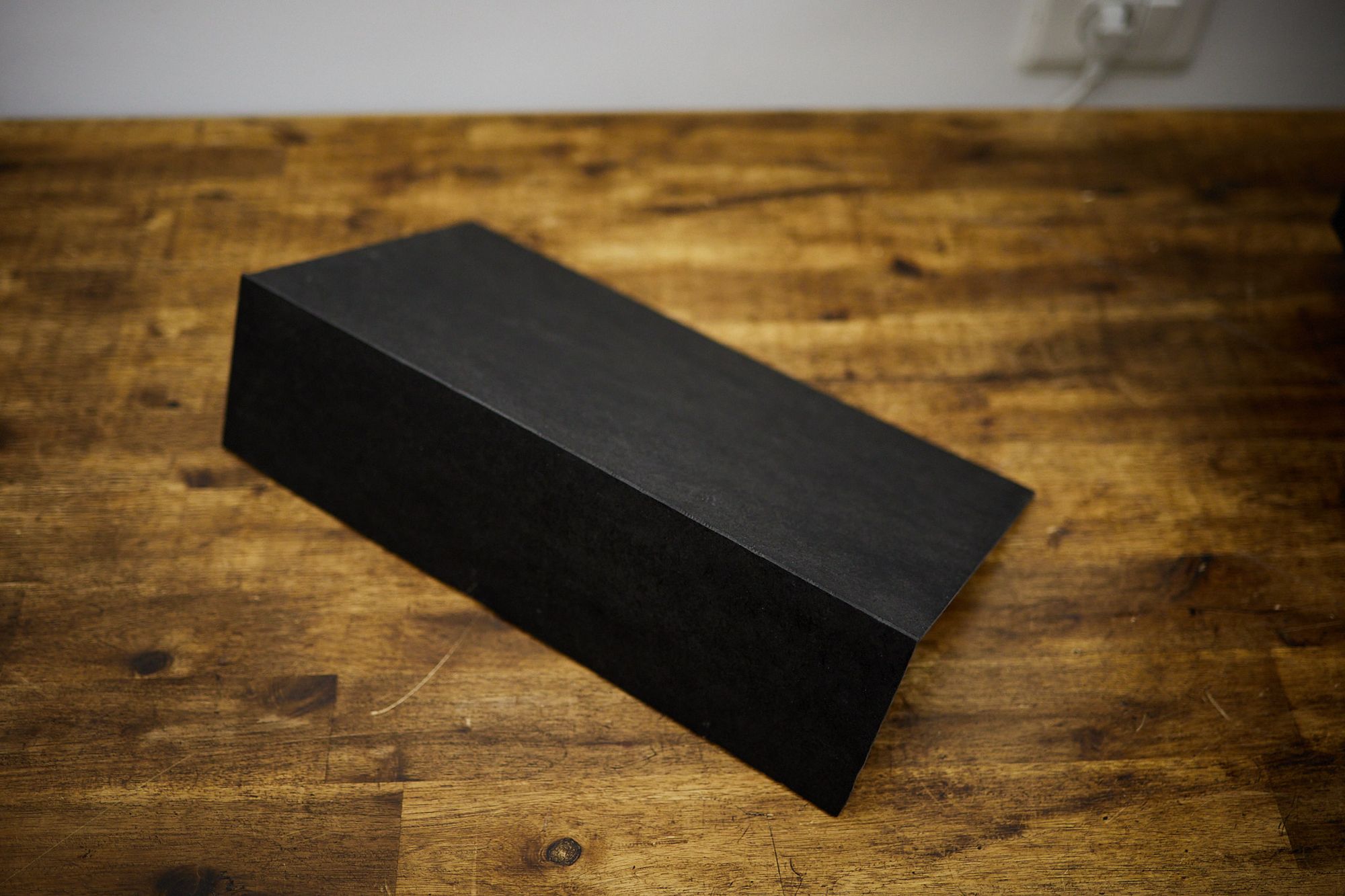
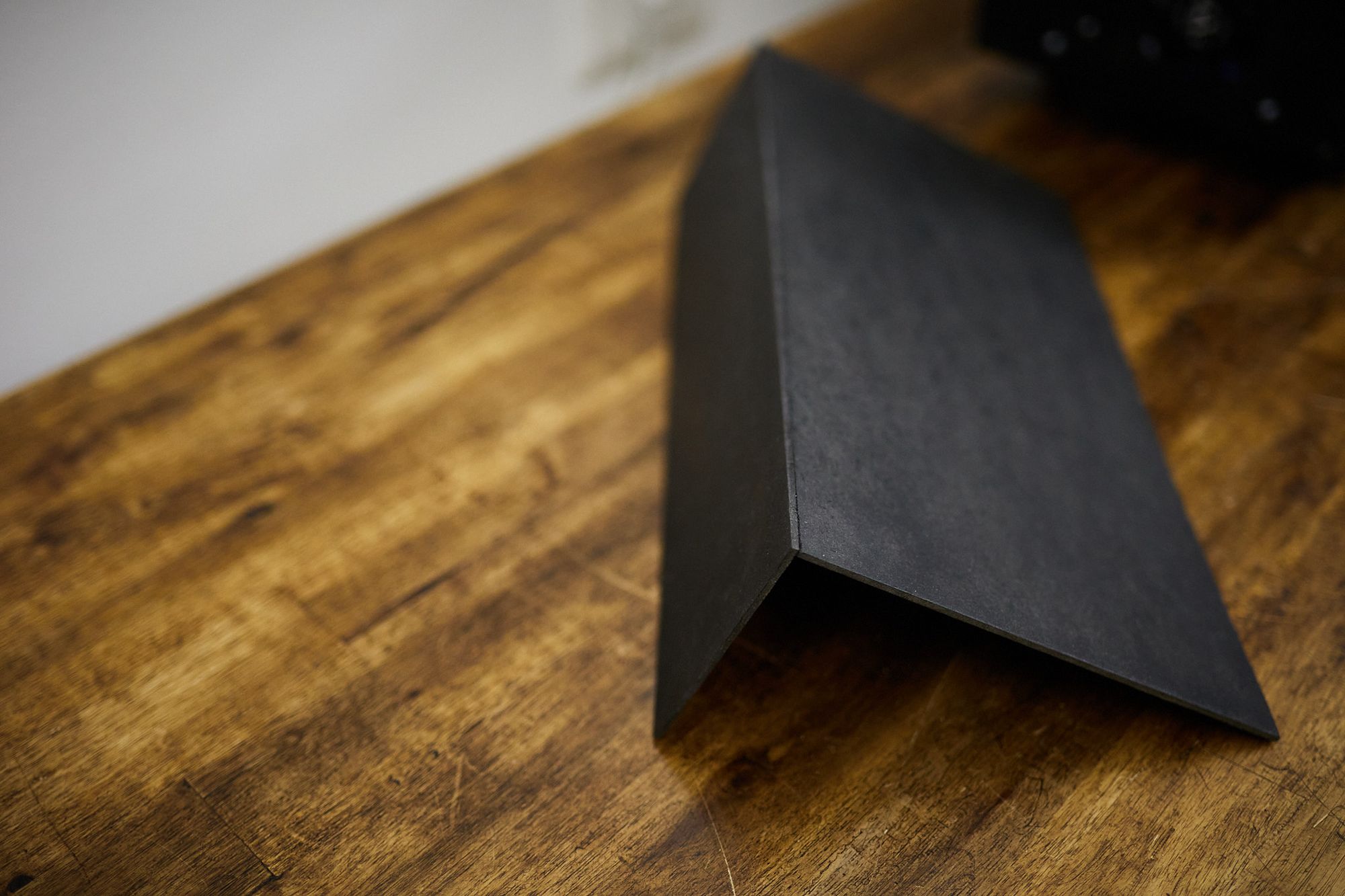
But I was not liking at all all that mess, so I build a little board cover to the PSU space. This way all the cables will be hidden from view, and also we will improve airflow through the PSU. At the end, it looked like this:
To connect the PSU to the main at the wall, I build a little board with a power connector and a 90mm fan to extract the heat from the PSU to the exterior of the case:
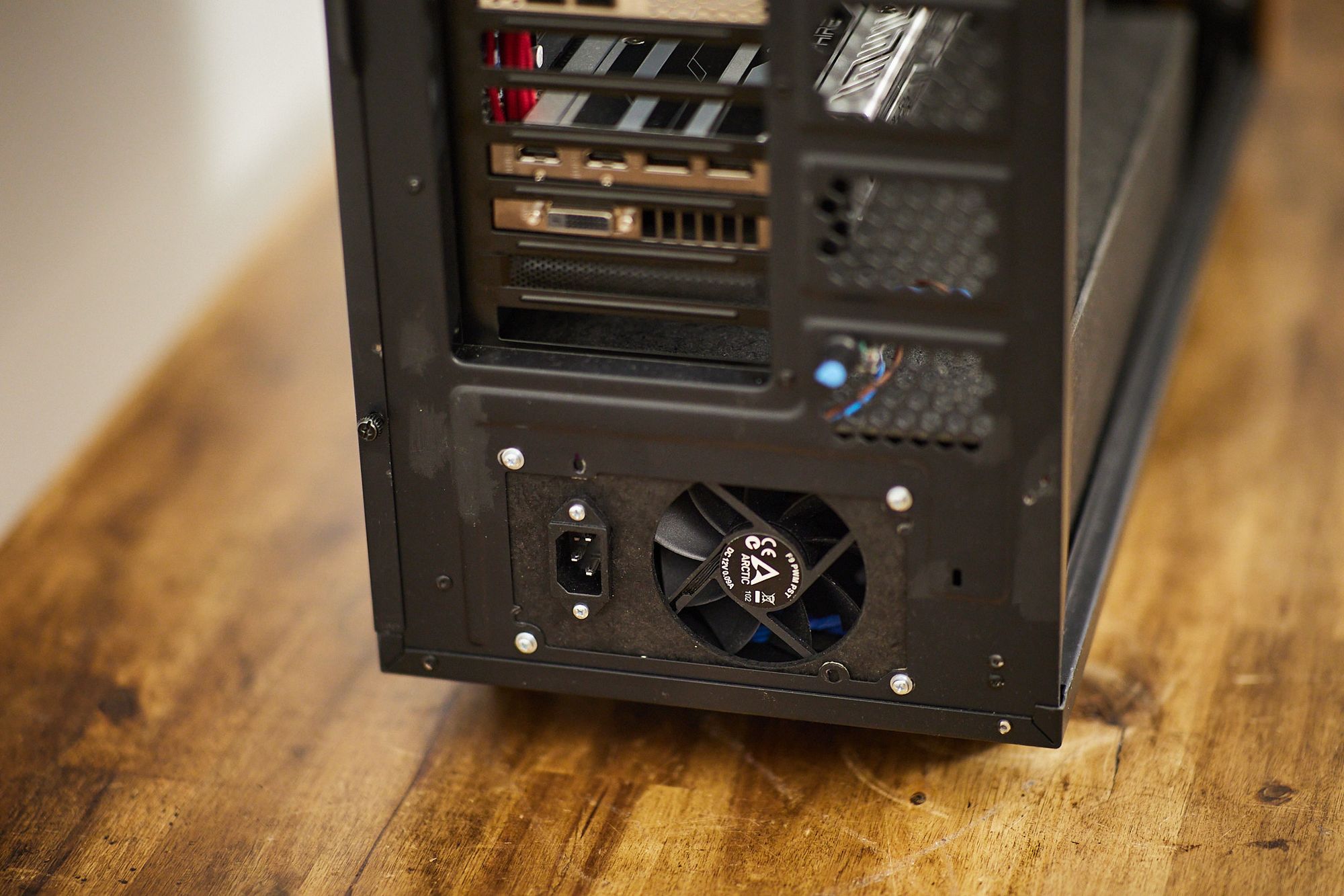
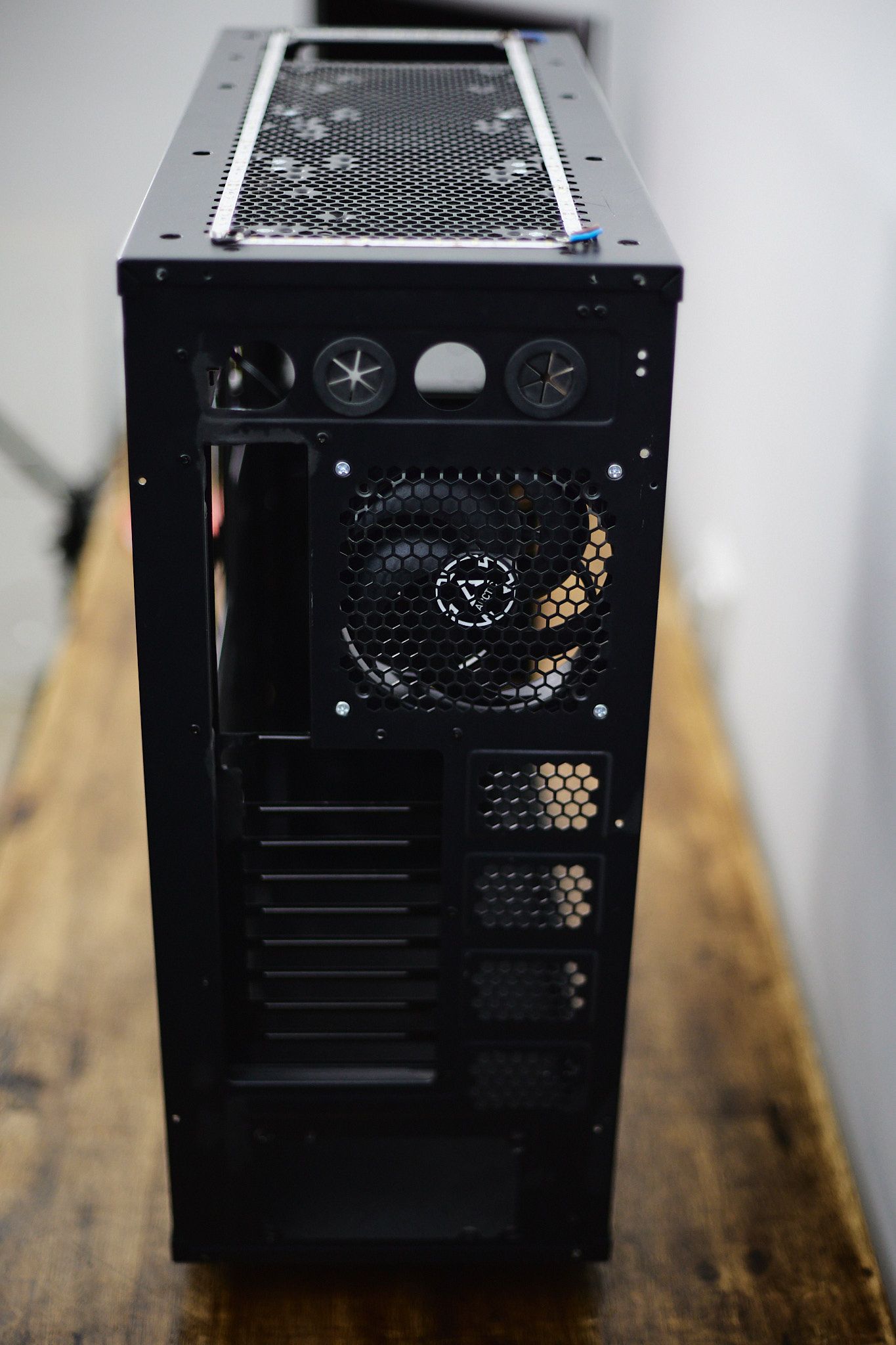
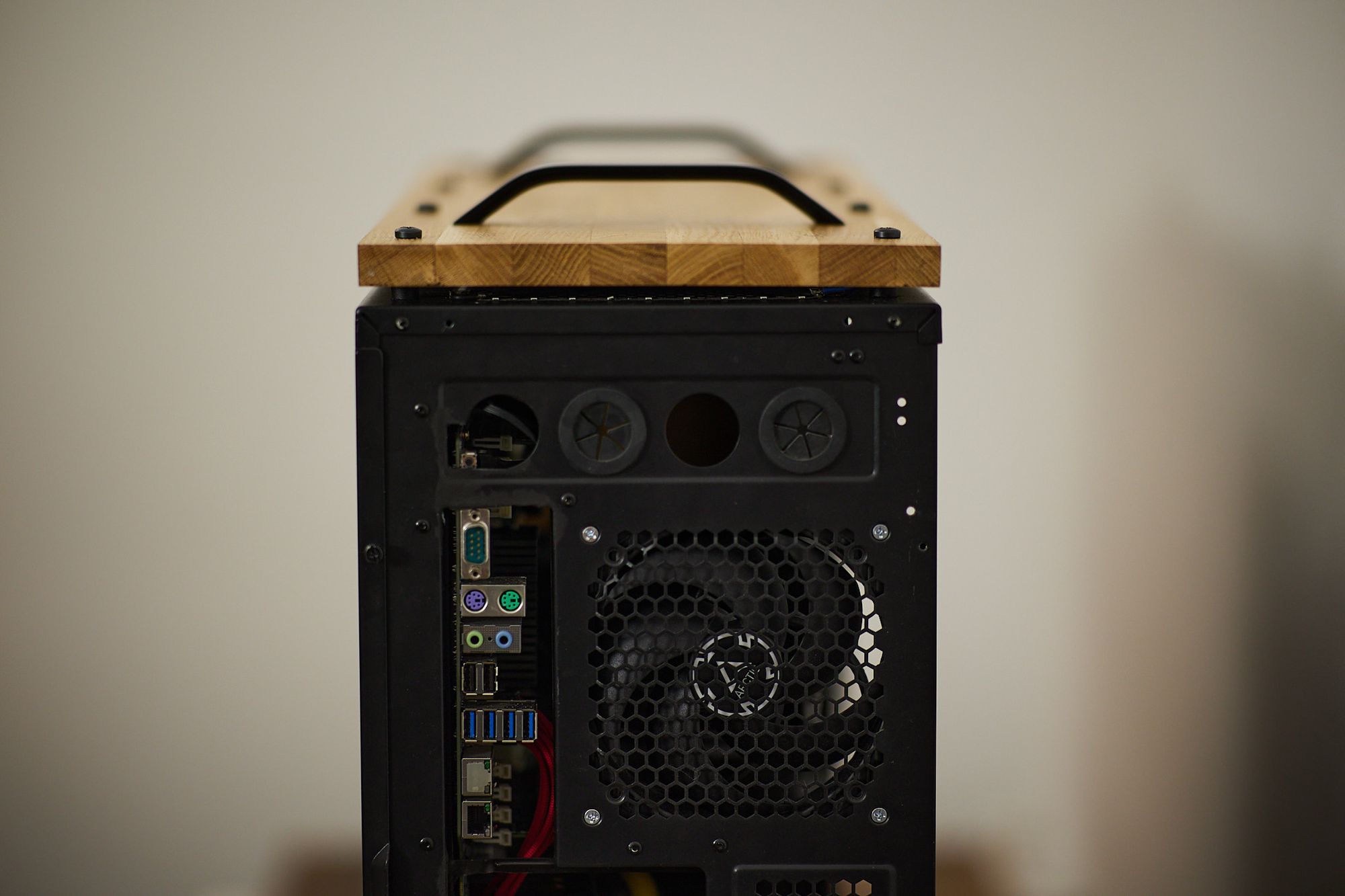
This is how the I/O of the motherboard look at the back of the case. I had to use the Dremel to cut a space at the top for the back power button:
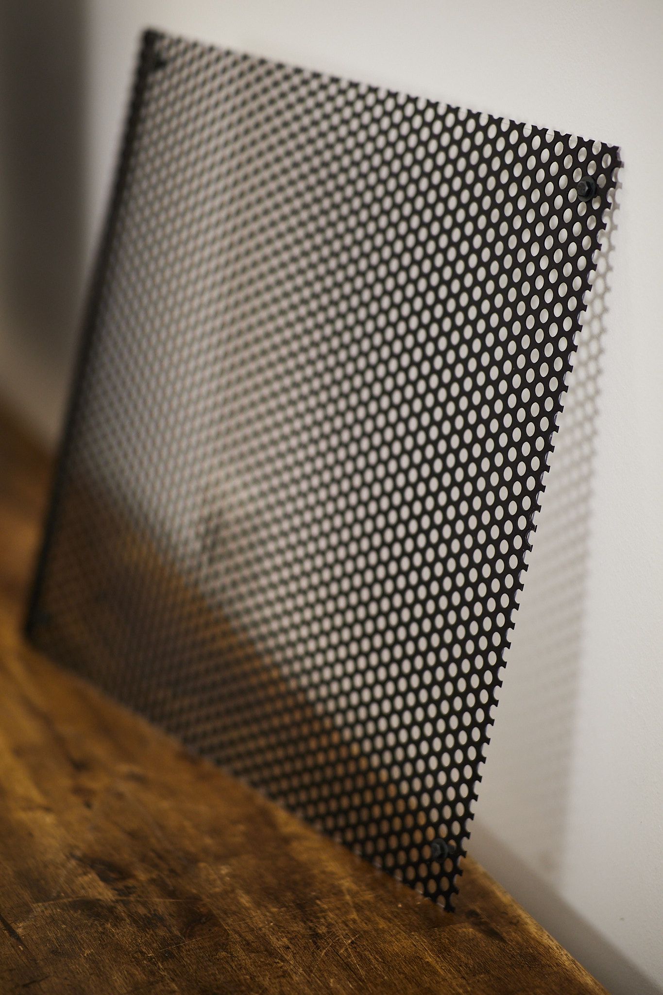
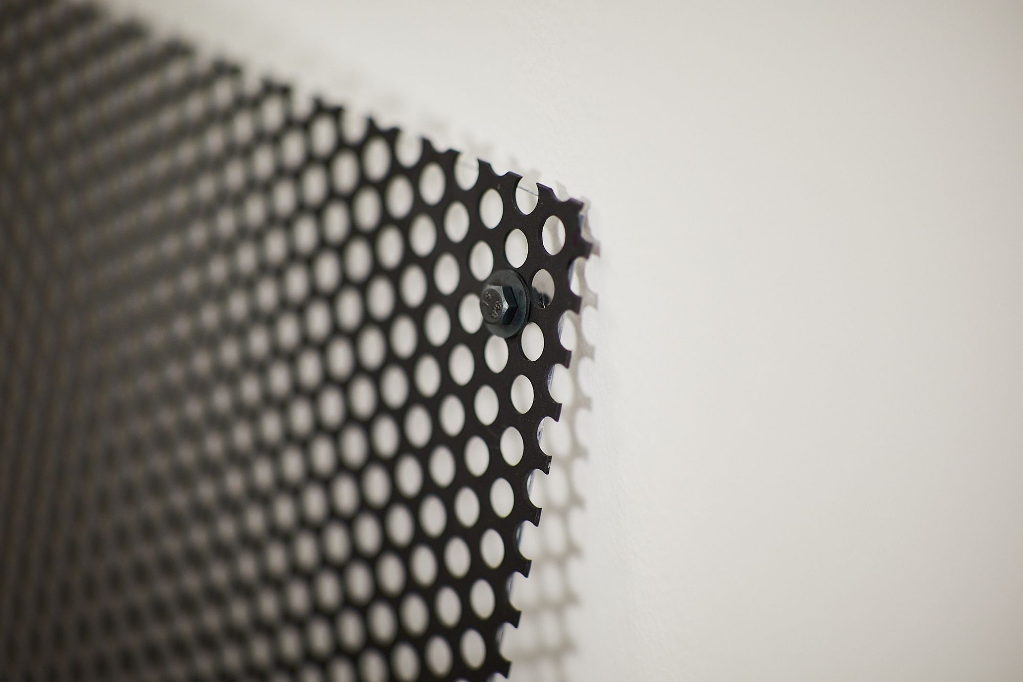
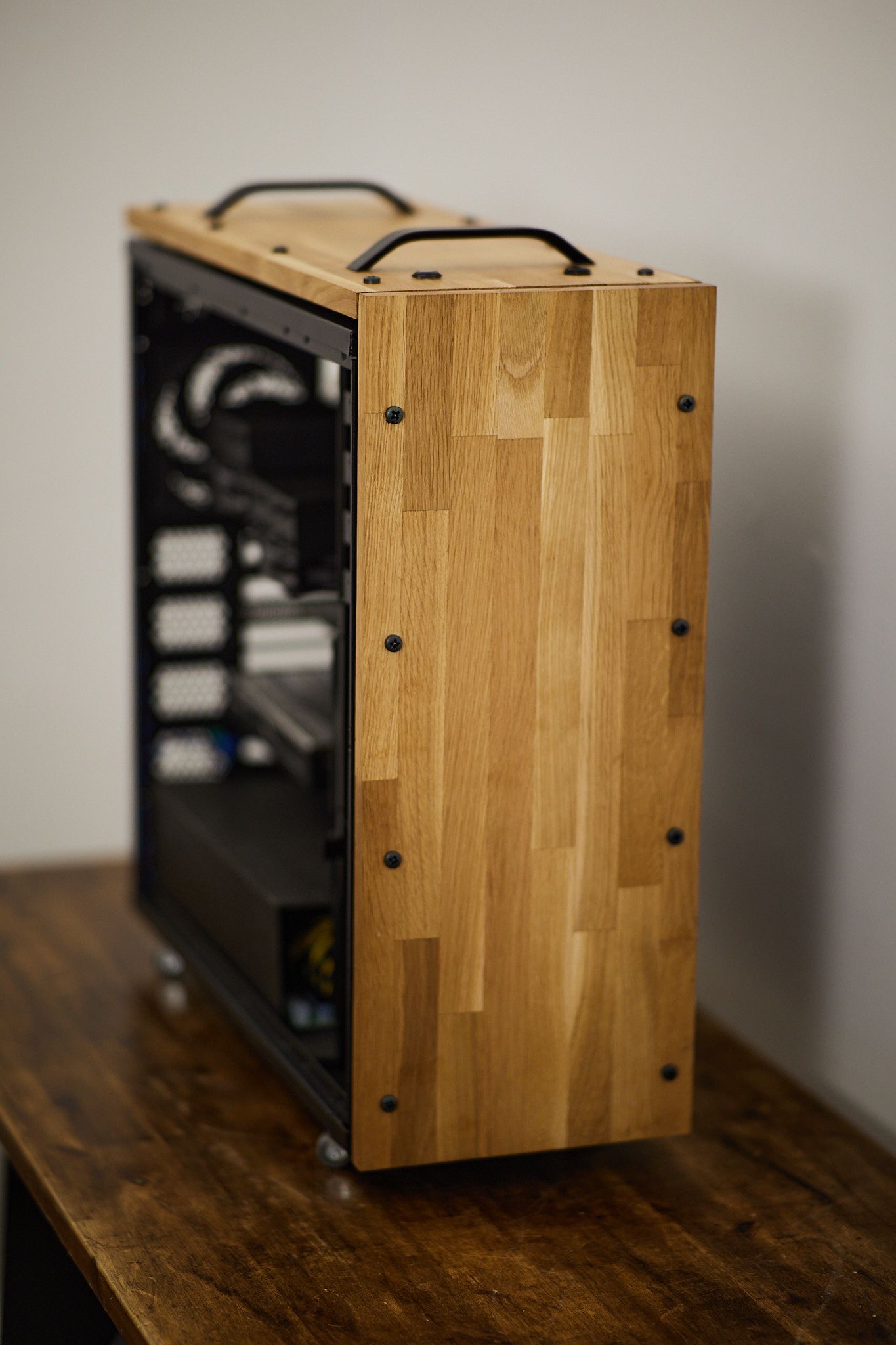
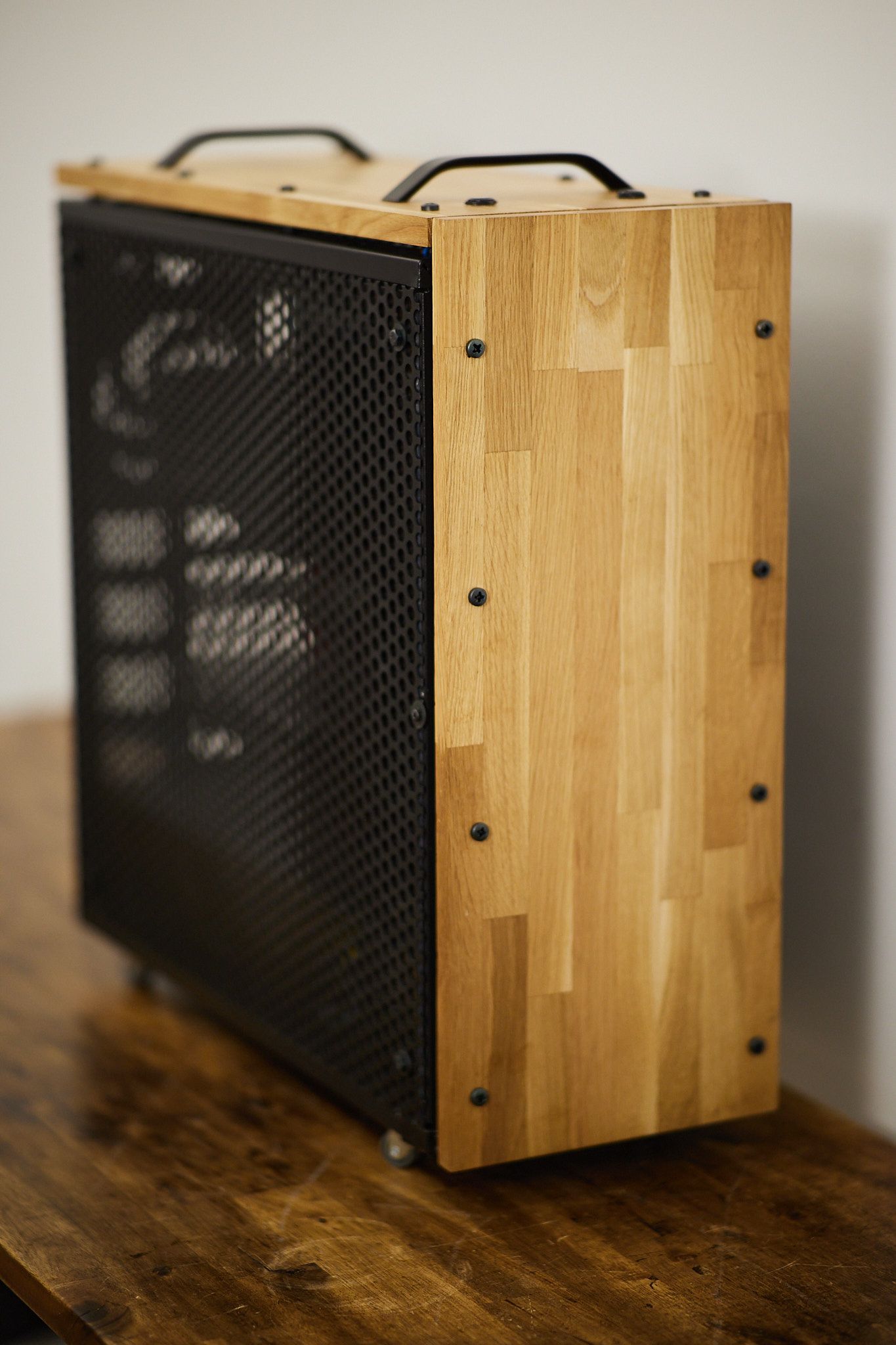
And then, as a final touch, the side panel. I ditched the original windowed one, which I always thought it looked hideous, and I made a new one using perforated 2mm width steel plank, which I painted black. I also attached a polycarbonate plastic board to it to assure air flows in the direction I want.
It looks like this:
And, finally, everything together, it looks like this:
5. Conclusion
This was a long project. A couple of months actually, after all the tampering and fiddling with the pinouts, the multimeter and the power supply. But at the end the thing is working perfectly: no errors at all at boot, fans are controlled by the motherboard using its own PWM signals, the PSU is very high quality as it is server level, and finally the case is awesome.
I could not hope for a better system for the amount of money I've paid for it.
So... I hope you guys like it, and I will see you again in the next project :)
Have fun.